4. B modeling#
4.1. Characteristics of modeling#
In this modeling, still 3D, we consider the case X- FEM. The crack is no longer meshed, it is introduced into the healthy mesh by the operator DEFI_FISS_XFEM.
4.2. Characteristics of the mesh#
The structure is modelled by a regular mesh composed of \(5\times 30\times 50\) HEXA8, respectively along the \(x,y,z\) axes (see [Figure 4.2-a]). It can be observed that the cells affected by the crack are partitioned into tetrahedra by the operators X- FEM for the purposes of numerical integration of quantities such as mass and stiffness.
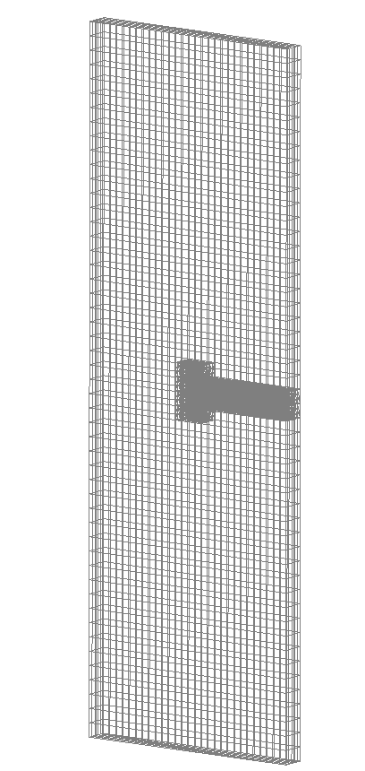
Figure 4.2-a: The mesh for modeling B
4.3. Tested sizes and results#
For this modeling, tests on the natural frequencies of the first 8 modes are considered with the results obtained from modeling A.
Identification |
Reference |
Code_Aster |
% difference |
|
Frequency mode 1 |
1.363 |
1.363 |
0.057 |
|
Frequency mode 2 |
3.220 |
3.220 |
3.179 |
1.3 |
Frequency mode 3 |
4.815 |
4.815 |
4.817 |
0.067 |
Frequency mode 4 |
7.195 |
7.195 |
7.203 |
0.12 |
Frequency mode 5 |
10.098 |
9.957 |
1.4 |
|
Frequency mode 6 |
11.789 |
11.789 |
11.629 |
1.4 |
Frequency mode 7 |
17.484 |
17.484 |
17.414 |
0.40 |
Frequency mode 8 |
18.281 |
18.281 |
18.253 |
0.16 |
4.4. notes#
As can be observed in the comparison of the results for this modeling, we obtain fairly small differences between the natural frequencies calculated with the X- FEM model and those calculated with the classical model. These differences are normal knowing that the mass, the elastic stiffness as well as the geometric contribution of the stiffness are calculated differently for the elements X- FEM. These are partitioned into tetrahedra on which integration schemes different from classical elements are considered. With regard to modal deformations, we note (see Figure 4.5-a) a very good agreement between the results obtained from the classical calculation and those obtained from the calculation X- FEM.
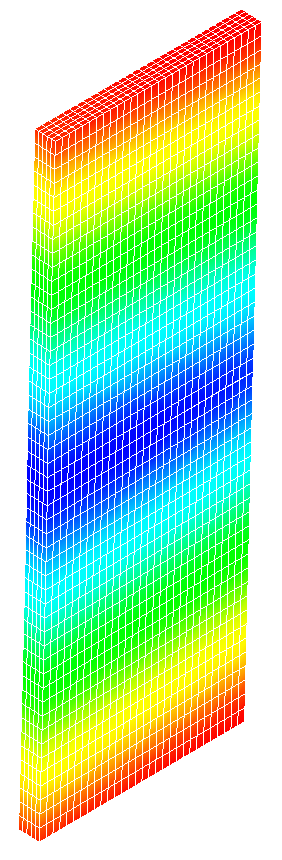
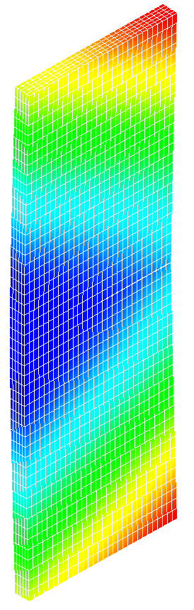
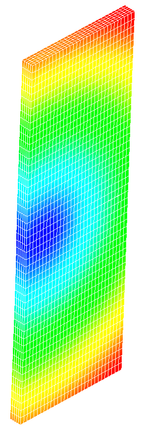
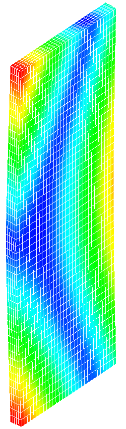
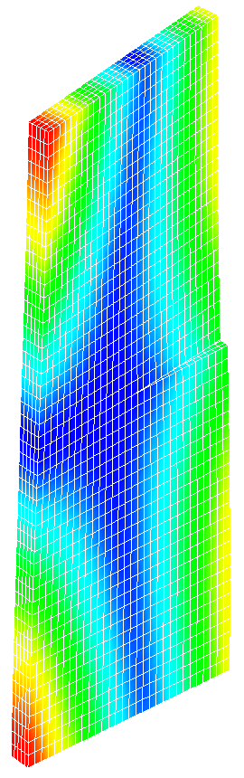
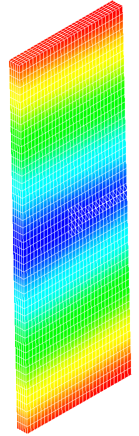
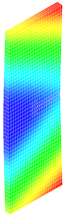
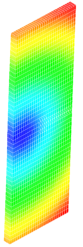
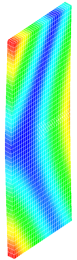
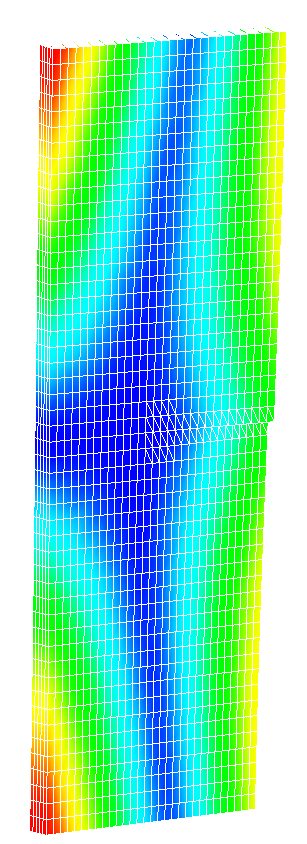
Figure 4.5‑a: The modal deformations for the first 5 natural modes. On the top row are the « classic » modes and on the bottom row are the « X- FEM » modes