3. Modeling A#
3.1. Characteristics of modeling#
A 3D modeling with the mesh crack is considered and the classical finite element method is used to perform the calculation. This modeling will serve as a reference and will allow comparison with the X- FEM method.
3.2. Characteristics of the mesh#
The structure is modelled by a regular mesh composed of \(5\times 30\times 50\) HEXA8, respectively along the axes \(x\) , \(y\) , \(z\) (see [Figure 3.2-a]). The two superimposed surfaces are the lips of the crack.
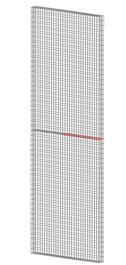
Figure 3.2-a: The mesh for modeling A
3.3. Tested sizes and results#
For this modeling, non-regression tests on the natural frequencies of the first 8 modes are considered.
Identification |
Reference |
Code_Aster |
% difference |
|
Frequency mode 1 |
1.363 |
1.363 |
1.363 |
|
Frequency mode 2 |
3.220 |
3.220 |
3.220 |
|
Frequency mode 3 |
4.815 |
4.815 |
||
Frequency mode 4 |
7.195 |
7.195 |
7.195 |
|
Frequency mode 5 |
10.098 |
10.098 |
10.098 |
|
Frequency mode 6 |
11.789 |
11.789 |
11.789 |
|
Frequency mode 7 |
17.484 |
17.484 |
17.484 |
|
Frequency mode 8 |
18.281 |
18.281 |
18.281 |