3. Geometric pairing problem#
3.1. Introduction#
The first problem to be addressed in the case of contact is to define reliably and robustly which parts of the two surfaces are likely to come into contact. This is the so-called matching operation, common with the mixed hybrid formulation called the « continuous » method presented in document [R5.03.52].
There are two types of pairing available in*Code_Aster*:
Nodal pairing;
The master-slave pairing (or node-facet).
Nodal pairing (APPARIEMENT =” NODAL “) requires that the relative displacement between a slave node and the master node that is paired with it, projected in the direction of the normal to the slave node, be less than the initial play in that direction. The use of this formulation is not recommended because it requires to have compatible meshes (nodes « in front ») that remain compatible during the deformation (hypothesis of small slips), and for which the master and slave normals are approximately collinear. Without these hypotheses, the approximation made becomes risky and it is preferable to use the knot-facet formulation.
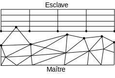
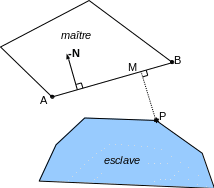
The master-slave pairing, chosen by the keyword APPARIEMENT =” MAIT_ESCL “, does not grant an equivalent role to the two surfaces: the surface (\({S}_{1}\)) described under GROUP_MA_MAITou MAILLE_MAIT is called the master surface and the surface (\({S}_{2}\)) is the slave surface. The non-interpenetration conditions express that the nodes of the slave surface (stars in figure ()) do not penetrate the meshes of the master surface. On the other hand, we can see that it is possible for the master nodes (circles) to penetrate the slave surface.
|
Figure 3.1-a : master surface and slave surface. |
Note:
Slave nodes are by default all the nodes belonging to the contact meshes defining the slave surface. The keywords SANS_NOet SANS_GROUP_NOpermettent to give, zone by zone, a list of nodes that should be removed from the list of slave nodes. This makes it possible to remove knots that are subject to Dirichlet boundary conditions that are incompatible with contact (see § 7.2).
3.2. Definition of potential contact areas#
Code_Aster does not have a mechanism for automatically detecting potential contact areas, so it is up to the user to define a priori the areas that he predicts will come into contact with. These areas must be large enough not to observe interpenetration. It should be noted that the matching phase is an inexpensive operation in general (much less expensive than solving the mechanical contact problem) and that it is therefore possible to define sufficiently large areas without risking to penalize performance, provided that certain precautions are respected to ensure, in particular, the uniqueness of the projections.
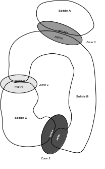
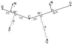
We consider the three solids in figure (), represented in 2D. Three possible areas of interpenetration between solids have been defined: one zone between solid \(A\) and solid \(B\), and two zones between solid \(B\) and solid \(C\). The user, who defines these areas in the command file, assumes here that outside of these areas, there is no risk of interpenetration, taking into account the load.
|
Figure 3.2-a : definition of three contact areas. |
Each contact zone is defined in the DEFI_CONTACT operator, the ZONE factor keyword. By definition, a zone consists of two surfaces whose interpenetration is sought to be prevented: the first is defined under the keyword GROUP_MA_MAIT (or MAILLE_MAIT), the second under the keyword GROUP_MA_ESCL (or MAILLE_ESCL), that is to say by the data of the edge cells that constitute them. These meshes are SEG2ou, SEG3pour a 2D mesh, TRIA3, TRIA6, QUAD4, QUAD8ou QUAD9pour a 3D mesh.
Notes:
The edge meshes required for contact will not be created by*Code_Aster from the solid elements and must therefore already exist in the mesh file.
The choice of surfaces that will be masters or slaves is important. Information on this topic is available in the documentation [U2.04.04].
3.2.1. Special case of contact for a cable or a 3D beam#
It is possible in 3D to treat the contact between a SEG2ou SEG3 mesh (modeling a cable or a beam) and a surface. In this case, it is imperative to use the “MAIT_ESCL” matching method and provide the segments under the GROUP_MA_ESCL keyword (slave cells). The section of the beam can then be taken into account by using the keyword DIST_ESCL (cf. § 3.6).
3.2.2. Case of nodal pairing#
You should choose to take as a slave surface the one with the fewest nodes (an error message will stop you if your master surface contains fewer nodes than your slave surface), in order to maximize the chances of having an injective match (a master node is only paired with one slave node). The master node paired with each slave node is determined by a nearest neighbor calculation explained in § 3.4.2. We use the normal to the master node to write the non-interpenetration relationship.
Even in the case of nodal pairing, contact surfaces are defined in terms of meshes. The slave and master nodes are then the nodes of the meshes thus defined.
3.3. Orientation of the normals#
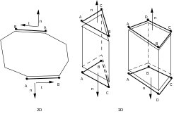
It is imperative that the contact meshes be defined so that the normal is outgoing: the connectivity of the segments must be defined in order \(\mathrm{AB}\), that of the triangles in order \(\mathrm{ABC}\), and that of the quadrangles in the order \(\mathrm{ABCD}\), and that of the quadrangles in the order, as shown in the figure. For a better reading of the drawing, we have here slightly removed the edge mesh used in contact with the « face » of the 2D or 3D solid element on which it is based. To do this, you can use the MODI_MAILLAGE operator, options ORIE_PEAU_2D, ORIE_PEAU_3D or ORIE_COQUE.
|
Figure 3.3-a : contact mesh numbering to have an outgoing normal. |
3.4. Matching algorithm#
3.4.1. Principle#
The matching algorithm involves two steps:
For each slave node we look for the nearest master node;
We then look for the master mesh attached to the previously determined master node that is closest to the slave node;
In the case of nodal pairing, of course, only the first step is being done.
3.4.2. Finding the nearest neighbor of a node#
This phase is common to both formulations: knot/facet and knot/node. The method used to find the master node closest to a slave node is very simple: all you have to do is calculate the distance (in updated geometry, see § 3.7) between the slave node and the candidate master nodes.
3.4.3. Search for the paired master stitch#
The algorithm for finding the master mesh that is paired with the slave node is as follows:
Knowing the master node closest to slave node \(P\) (see § 3.4.2), we examine successively the master cells containing this node.
For each mesh thus identified, we look for the orthogonal projection \(M\) of the slave node \(P\) on the master mesh.
The mesh minimizing the \(\mathit{PM}\) distance is chosen to be matched to the slave node.
Notes:
If the slave node is projected outside a master mesh, its projection is folded back onto this mesh under certain conditions (see § 3.4.5).
If at least one projection takes place inside a master mesh, then this one will be preferred to a projection leading to a drawdown (regardless of the distance measured)
If all the projections of the slave node take place outside their respective master mesh, the slave node is considered to be unpaired and will therefore be excluded from the resolution phase
3.4.4. Calculating the projection of the slave node on the master mesh#
3.4.4.1. Notations#
The parts of surfaces \(\partial {\Omega }^{i}\) likely to come into contact during the deformation of the two solids are noted \({\gamma }_{c}^{i}\). It is assumed the existence of regular maps marked \({\Theta }^{i}\) describing surfaces \({\gamma }_{c}^{i}\). These maps are defined as follows:
where \({\omega }^{i}\) is a bounded (reference) domain contained in \({ℝ}^{2}\) (it is the parametric reference space of the finite element). Moreover, \({\varphi }^{i}\) refers to the transformation of solid \({B}^{i}\), defined by:
We are always setting ourselves at a fixed \(t\) time. The master surface is noted \({\gamma }_{c}^{1}\) and the slave surface is noted \({\gamma }_{c}^{2}\). The pairing is carried out by looking for, for any point \(\left\{{x}^{i}\right\}\mathrm{=}{\varphi }^{i}({p}^{i},t)\) of the \({\gamma }_{c}^{1}\) border, for the nearest point \(\left\{\tilde{x}\right\}\) of \({\gamma }_{c}^{2}\). This amounts to solving the following constrained optimization problem. For any \(\left\{{x}^{1}\right\}\mathrm{=}{\varphi }^{1}({\Theta }^{1}({\xi }_{1}^{1},{\xi }_{2}^{1}),t)\) point with \(({\xi }_{1}^{1},{\xi }_{2}^{1})\mathrm{\in }{\omega }^{1}\), and for all \(t\ge 0\), find \(\tilde{{\zeta }_{t}}\mathrm{=}({\xi }_{1}^{2},{\xi }_{2}^{2})\mathrm{\in }{\omega }^{2}\) such as:
: label: eq-27
{tilde {zeta}} _ {t}mathrm {=}mathrm {=}underset {({xi} _ {2} _ {2})mathrm {in} {2})mathrm {in} {in} {omega} {omega} {omega} ^ {2}} {omega} ^ {2}} {omega} ^ {2}} {omega} ^ {2}} {omega} ^ {2}} {omega} ^ {2}} {omega} ^ {2}} {omega} ^ {2}} {omega} ^ {2}} {omega} ^ {2}}} {text {argmin}}}left{frac {1} {2}.} ≡ {varphi} ^ {1} ({Theta}} ^ {1} ({xi} _ {1} ^ {1}, {xi} _ {2} ^ {1}), t)mathrm {-} {-} {varphi} ^ {1} {1} {1} {1} {1} {1} {1} {1} {1} {1} {1} {1} {1} {1} {1} {1} {1} {1} {1} {1} {1} {1} {1}), t)mathrm {-} {-} {varphi} {1} {-} {varphi} ^ {1}} {2}, {xi} _ {2}, {xi} _ {2} ^ {2}), t) thur {2} ^ {}right}
Solution \(\tilde{{\zeta }_{t}}\) is the position in the parametric reference space of the \(M\) projection of the projection of the slave node \(P\) onto the master mesh.
3.4.4.2. Formulation of the minimization problem#
To solve the non-linear problem (), it is proposed to use a Newton minimization algorithm. The problem is reformulated as follows: for a given slave node we look for the point (in parametric coordinates) that minimizes the distance to a given master mesh (the one defined in paragraph § 3.4.3).
We note \(f\) the \({L}_{2}\) norm of the distance between a slave node located in \(\left\{{x}_{e}\right\}\) and a point \(\left\{{x}_{m}\right\}\) belonging to the master mesh facing each other:
: label: eq-28
f (left{{x} _ {m}right})mathrm {=} {=>left{{x} _ {e}right}mathrm {-}mathrm {-}left{{x}left{{x} _ {m}right{x} _ {m}right{x} _ {e}rightright}right}rightright}right}right}right-}mathrm {-}left{{x}left{
We write the functional in parametric space, \(\left\{{x}_{m}\right\}\) being expressed from the \({\mathit{nb}}_{\mathit{no}}\) nodes \(\left\{{x}_{i,m}\right\}\) of the paired master mesh:
It is this quantity that must be minimized. We apply Newton’s algorithm to the stationarity conditions (Euler-Lagrange) of the minimization problem thus stated, that is to say to the vector functional \(\left\{\mathrm{\nabla }f(\left\{\zeta \right\})\right\}\), an expression of the Taylor expansion in the first order, around the point \(\left\{{\zeta }_{0}\right\}\):
: label: eq-30
left{mathrm {nabla} f (left{zetaright})right}right}underset {text {linearization}} {mathrm {=}}left{mathrm {abla} f (left{zeta}}right}} {mathrm {abla} f (left{{zeta}} _ {0}right})right}}right}}left [H ({zeta} _ {0})right]mathrm {.} (left{zetaright}mathrm {-}left{{zeta} _ {0}right})
Where \(\left[H\right]\) is the Hessian matrix of the second derivatives of \(f\) and \(\left\{\mathrm{\nabla }f(\left\{\zeta \right\})\right\}\) is its gradient. A minimum of \(f\) occurs when its gradient is zero.
The iterative algorithm is then written as:
Start from the initial point \(\left\{{\zeta }_{i=0}\right\}\) on the master stitch. This starting point is simply chosen in \(\left\{{\zeta }_{i=0}\right\}=\left\{0\right\}\);
Evaluate the \(\left\{\nabla f\left(\left\{{\zeta }_{i}\right\}\right)\right\}\) gradient and the \(\left[H\left({\zeta }_{i}\right)\right]\) Hessian matrix at this point;
Calculate the direction of descent \(\left\{{d\zeta }_{i}\right\}=-{\left[H\left({\zeta }_{i}\right)\right]}^{-1}\mathrm{.}\left\{\nabla f\left(\left\{{\zeta }_{i}\right\}\right)\right\}\)
Calculate linear search parameter \(\alpha\) (see § 3.4.4.4)
Calculate the next point such as \(\left\{{\zeta }_{i+1}\right\}=\left\{{\zeta }_{i}\right\}+\alpha \left\{{d\zeta }_{i}\right\}\);
If the process has converged, we stop, otherwise we loop in 2.
Notes:
This problem can be written without constraints;
The uniqueness of the solution cannot be guaranteed; Newton’s process will find the first point achieving the conditions of stationarity.
The existence of the gradient and the Hessian matrix is ensured if the mesh is sufficiently regular, which is always the case on a finite element mesh that is not too distorted.
The iterative process is stopped by a criterion on the displacement increment in parametric space \(\epsilon =\frac{\sqrt{\langle {\zeta }_{i+1}\rangle \left\{{\zeta }_{i+1}\right\}-\langle {\zeta }_{i}\rangle \left\{{\zeta }_{i}\right\}}}{\sqrt{\langle {\zeta }_{i+1}\rangle \left\{{\zeta }_{i+1}\right\}}}\) with \(\mathrm{\epsilon }\le {\text{10}}^{-4}\) (value that cannot be modified by the user). Since this value is estimated in relation to the parametric coordinates, there are no problems with the size of the cells and the units used.
The maximum number of Newton iterations is set to \(200\) (value cannot be modified by the user).
If the maximum number of iterations is reached, we select as projected the iterate that minimized the distance between the slave node and the master mesh (it is therefore not perfectly the orthogonal project).
There is a variant in which the search direction is not estimated by Newton’s algorithm but a fixed direction given by the user, which can be useful in some difficult cases (perfectly convex mesh that does not give a single projection for example). It is activated by the keyword TYPE_APPA =” FIXE “and the vector is given by DIRE_APPA.
Projection on 3D segment elements (in the case of beams or cables) requires a definition of normal by the user using the keywords VECT_MAIT/VECT_ESCL.
3.4.4.3. Expression of the tangent matrix and the residue#
The expressions of the terms used in the writing of the Newton algorithm described above are given below. We recall the functional one:
: label: eq-31
fleft ({xi} _ {1}, {xi} _ {2}right) =fleft (left{zetaright}right) = {left{{x} _ {{x} _ {e} _ {e}right} _ {e}right} _ {mathit {no}} _ {mathit {no}} _ {mathit {no}} _ {e}right_ {e}right_ {e}right_ {e}rightright} _ {e}rightright} -sum _ {i=1}} ^ {mathit {nb}} _ {mathit {no}}} {varphi}} _ {i}left (left{zetaright}right)mathrm {.} left{{x} _ {i, m}right}} ^ {2}
The gradient of this functional:
: label: eq-32
left{nabla fleft (left{zetaright}right}right)right} =left{begin {array} {c}frac {partial f} {partial f} {partial f} {partial f} {partial f} {partial f}}frac {x}}frac {partial f} {partial f} {partial f} {partial f} {partial f} {partial f} {partial f} {partial f} {partial f} {partial f} {partial f} {partial f} {partial f} {partial f} {partial f} {partial f} {partial f} {partial f} {partial f} {
The terms are spelled explicitly:
The hessian of this functional:
The terms are spelled explicitly:
And for cross terms:
3.4.4.4. Linear search in the projection algorithm#
To improve the robustness of the projection algorithm, a linear search phase is added to the Newton algorithm (cf. § 3.4.4.2). Given a descent direction \(\left\{{d\zeta }_{i}\right\}\), it is a question of determining an advance parameter \(\alpha\) that minimizes a functional \(F\) associated with \(f\).
The linear search algorithm used (linear search with reverses and Armijo’s rule) is the same as for the implicit integration of laws of behavior [R5.03.14].
Functional \(F\), associated with the distance functional \(f\) defined in, is as follows:
To choose \(\alpha\), we are in fact not going to try to minimize exactly the functional \(F\) but an approximation of this one (quadratic, cubic). To know which approximation to use, we rely on Armijo’s rule. For more details, refer to [R5.03.14] and [14] which detail the implementation of such an algorithm.
For the linear search implemented in the projection algorithm, the parameters chosen (hard copy) are as follows:
Armijo rule parameter |
\(\omega =\mathrm{0,0001}\) |
Min. terminal for folding |
\({\alpha }_{\mathit{min}}=\mathrm{0,1}\) |
Max folding terminal |
\({\alpha }_{\mathit{max}}=\mathrm{0,5}\) |
Maximum number of cubic interpolations |
\({\mathit{it}}_{\mathit{max}}=2\) |
These parameters in particular mean that if the step by default (\(\alpha =1\)) does not satisfy the Armijo rule, that is to say that the chosen direction of descent does not approximate the orthogonal project, then \(\alpha\) will be at most equal to \(\mathrm{0,5}\). This choice makes it possible to promote robustness (avoid following an erroneous research direction) rather than performance (values of \(\alpha\) greater than \(1\)).
For poor quality meshes, with distorted meshes, linear search has shown its value, finding the right orthogonal projection on difficult cases where an algorithm without a linear search failed.
3.4.5. Treatment of projections outside the mesh#
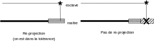
There are projections whose results are sensitive to purely numerical parameters or whose existence and mathematical uniqueness are not guaranteed as a step. Under certain conditions, it is possible to detect contact between two surfaces when there is none. The problem first comes from an incorrect and imperfect definition of the surfaces that are likely to come into contact. Take the case of contact in 2D (contact surfaces are therefore segments) where a slave node must project outside the master surface (see figure):

|
Figure 3.4.5-a : projection out of a master mesh. |
The user can choose to « re-project » this slave node onto the extended master mesh or not to do so (see figure).
|
Figure 3.4.5-b : principle of the tolerance zone for projection onto a master mesh. |
The limit value of this re-projection is set by the keyword TOLE_PROJ_EXT, which takes as argument the value (relative to the reference element) of the extension of the master mesh in which the re-projection is authorized. By default, this value is set to \(0.50\). This means that any slave node that projects at a distance greater than half the length of the master mesh will not be re-projected. To completely forbid re-projection, simply set TOLE_PROJ_EXT to zero. This operator is valid in 2D and 3D. In the 3D case, it is the extension of a contact surface mesh, and, as one reasons in parametric space, the curvature of the edges of the elements is well taken into account.
Likewise, if the contact surfaces are too large, any slave node located behind the master mesh is paired. The concept of « front-back » is given by the orientation of the normals given by the user (see § 3.3). You can restrict this matched mesh search with the TOLE_APPA parameter, which specifies the maximum search distance for meshes that are « matchable » with the slave node.
3.4.6. Case of projection in a given direction#
When using option DIRE_APPA, the user can force the projection algorithm not to look for the minimum distance between a slave node and its orthogonal projection on the master surface, but to simply find the point on the master surface linked to the slave node by a given vector. In this case the algorithm is as follows:
Start from the initial point \(\left\{{\zeta }_{i\mathrm{=}0}\right\}\) on the master stitch. This starting point is simply chosen in \(\left\{{\zeta }_{i\mathrm{=}0}\right\}\mathrm{=}\left\{0\right\}\);
Construct the Newton matrix \(\left[H({\zeta }_{i})\right]\) using the direction given by DIRE_APPA;
Construct the second member of Newton \(\left\{R\left(\left\{{\zeta }_{i}\right\}\right)\right\}\) by the difference between the slave node and its projected onto the master mesh;
Calculate the direction of descent \(\left\{{d\zeta }_{i}\right\}=-{\left[H\left({\zeta }_{i}\right)\right]}^{-1}\mathrm{.}\left\{R\left(\left\{{\zeta }_{i}\right\}\right)\right\}\)
Calculate the next point such as \(\left\{{\zeta }_{i+1}\right\}=\left\{{\zeta }_{i}\right\}+\left\{{d\zeta }_{i}\right\}\);
If the process has converged, we stop, otherwise we loop in 2.
Unlike the previous case, there is no linear search algorithm.
3.5. Kinematic relationships#
3.5.1. Definition of the contact matrix#
An idealized modeling of the contact phenomenon is carried out, in the sense that it assumes the boundaries of bodies perfectly defined by a line or a surface: we then write a discrete and linearized non-interpenetration condition [2]. Let \(P\) be a slave node, \(M\) its projection on the master mesh that was determined during the pairing. In 2D, this master mesh has two knots (SEG2) or three knots (SEG3). In 3D, it can have three, four, six, six, eight, or nine (TRIA3, QUAD4, TRIA6, QUAD8, QUAD9). The displacement of point \(M\) is a linear combination of the displacements of the nodes of the finite element, with the coefficients being the values of the functions of the form \(\Phi\) and \(M\). Let’s put ourselves in the case where the master stitch is a SEG2 to simplify the explanation. We then have:
Initially, we choose to take the outgoing normal of the master stitch as direction \(\left\{N\right\}\) (cf.).
|
Figure 3.5.1-a : projection of a slave node on a SEG2 mesh. |
The normal game is written as the difference between slave node \(P\) and its projection \(M\) on the master mesh:
If such a relationship is written for all contact couples, the geometric non-penetration conditions are obtained in matrix form:
The \(\left[{A}^{\text{c}}\right]\) matrix, called the contact matrix, contains one row per contact pair, and as many columns as the physical degrees of freedom of the problem. Suppose we have two contact meshes of type SEG2, according to the diagram in.
|
Figure 3.5.1-b : writing the contact matrix A on an example. |
If we note for example \({u}_{B}\) the movement of the node \(B\) in the direction \(x\), \({v}_{B}\) the movement of the node \(B\) in the direction \(y\), and \({d}^{1}\) and \({d}^{2}\) the current games for the two couples:
With contact matrix \(\left[{A}^{\text{c}}\right]\):
Only the degrees of freedom of the nodes involved in the contact were considered here; matrix \(\left[{A}^{\text{c}}\right]\) should be more sparse. But in practice, the contact matrix is always reduced to the active degrees of freedom. Therefore, only non-zero coefficients are stored.
3.5.2. Definition of the friction matrix#
The concept of contact matrix extends to the case of tangential slides, on the tangential plane. It is the \(\left[{A}^{\text{f}}\right]\) matrix of kinematic relationships of friction.
3.5.3. Choosing the normal#
In the previous paragraph, we chose to take the outgoing normal of the master stitch as direction \(\left\{N\right\}\). This is the default behavior in*Code_Aster*. However, it is possible to choose other normal ones:
The normal slave NORMALE =” ESCL “;
An average between normal master and normal slave NORMALE =” MAIT_ESCL “;
It is also possible to ask to use smooth normals (LISSAGE =” OUI “), i.e. instead of using the master normal at the projection point, we can take a normal resulting from the linear interpolation between the normals at the nodes of the master mesh.
Likewise, the calculation of normals is always done via the shape functions of the element, which is what we define as the « true » normal or the « automatic » normal. But it is possible to impose a normal on the master mesh, the slave mesh or on both in a different way:
Directly (VECT_MAIT or VECT_ESCL =” FIXE “)
Indirectly through the use of a trihedron (VECT_MAIT or VECT_ESCL =” VECT_Y “). In the latter case, the normal used will be the vector resulting from the vector product between the tangent to the mesh and the given vector VECT_Y.
Notes:
As this is a node-facet pairing, the slave normal is calculated itself by smoothing, so the LISSAGE option has no effect if we choose NORMALE =” ESCL “;
The use of predefined normals is mandatory in the case of beams;
The choice of a normal other than the master mesh should be limited to exceptional cases such as when the mesh or the compatibility problems of contact with the boundary conditions have forced the user to take as master a coarsely meshed surface;
The use of TYPE_APPA =” FIXE “to find the nearest master mesh (see § 3.4.4) does not prejudge the choice of the normal one when writing the non-penetration relationship, which remains at the user’s choice. But it’s more consistent to choose a fixed normal (VECT_MAIT =” FIXE “).
3.5.4. Contact matrix coefficients#
3.5.4.1. Standard elements#
The values of the \({\Phi }_{{B}_{j}}(M)\) shape functions of the master nodes at point \(M\) at point for the various contact meshes are standard (see [R1.01.01]).
3.5.4.2. Knitwear QUAD8#
Quadrilateral cells with eight knots have a defect. In fact, the functions of classical forms are not positive in the whole field and lead to aberrant results when they are used in contact. The main symptom associated with the use of classical form functions is the appearance of negative non-physical contact forces that cause oscillations (between vertex nodes and middle nodes).
To avoid this phenomenon, Code_Aster modifies element QUAD8en imposing linear relationships between middle nodes and vertex nodes and finally using the shape functions of QUAD4.
In general, it is best to avoid using this kind of element and to prefer complete quadratic elements like QUAD9, because QUAD8comme are considered linear elements and linear relationships are also introduced that can be annoying.
3.5.4.3. Elements of COQUE_3D#
Elements of type COQUE_3D are non-isoparametric mixed finite elements. They are based on quadratic cells of the QUAD9 type (respectively TRIA7) but since the middle node does not have a translational degree of freedom, we proceed to a projection onto a QUAD8 (respectively TRIA6) and we therefore come back to the defects mentioned in the previous paragraph. These finite elements are therefore not recommended in contact problems.
3.6. Introduction of a fictional game#
We may want to model the contact between structures with certain particularities (« hole » or « hump ») that we do not want to mesh (see figure).

|

|
Figure 3.6-a : holes and bumps. |
|
One solution consists in meshing the surface without these defects and in adding a distance given by the user (see figure).

|
Figure 3.6-b : flawless mesh surface. |
We correct the value of the game:
where \({d}_{\text{e}}\) and \({d}_{\text{m}}\) are given by the user respectively under the keywords DIST_MAIT and DIST_ESCL for each contact area. These distances are signed: they represent the translation to be applied to the mesh node in the direction of the outgoing normal \(\left\{n\right\}\) to obtain the point of the real structure. These keywords also make it possible to account for the contact between shells where only the average surfaces are meshed: \({d}_{\text{e}}\) and \({d}_{\text{m}}\) are then equivalent to the half-thickness of the shells (positive values).
Notes:
If DIST_MAIT and DIST_ESCL are used, care must be taken with the visual interpretation of the results. If \(({d}_{\text{e}}+{d}_{\text{m}})>0\), the code will be able to announce contact while the visualization will show a spacing of the two meshes. If \(({d}_{\text{e}}+{d}_{\text{m}})<0\), the code will be able to announce contact while the visualization will show two interpenetrating meshes;
To remember the signs, think of:
\(({d}_{\text{e}}+{d}_{\text{m}})>0\): addition of material in relation to the mesh
\(({d}_{\text{e}}+{d}_{\text{m}})<0\): removal of material in relation to the mesh
The options DIST_POUTRE and DIST_COQUE rely on the elementary characteristics defined in the AFFE_CARA_ELEM operator to add the fictional game corresponding to the thickness (in the case of shells) or to the radius (in the case of beams with a circular cross section).
3.7. Geometric update#
In the context of modeling contact during large movements, the evolution of the geometry of surfaces plays a fundamental role. In fact, it is it that conditions the calculation of the normals to the faces potentially in contact and therefore conditions the pairing made.
Geometric refresh is defined by the REAC_GEOM keyword from the DEFI_CONTACT command. Its operation is as follows:
If REAC_GEOM =” SANS “: there is no geometric update. All the calculation is done on the initial configuration with the initial pairing.
If REAC_GEOM =” CONTROLE “: you must enter NB_ITER_GEOM. Within the**same**no load, we perform NB_ITER_GEOM times the cycle*iteration until convergence, geometric update, pairing.
If REAC_GEOM =” AUTOMATIQUE “: the decision to redo a geometric match is made automatically by the software. The criterion is as follows:
RESI_GEOM is \(1\text{\%}\) by default. If the infinite norm of the displacement between two moments, divided by the infinite norm of the displacement obtained from the equilibrium is greater than RESI_GEOM, then we update. The infinite norm is defined by:
Notes:
At the first iteration or in case of rigid body movements (in dynamics), \({\mathrm{\parallel }\Delta {u}^{\mathrm{-}}\mathrm{\parallel }}_{\mathrm{\infty }}\mathrm{=}0\). To avoid dividing by zero, we force the update;
The infinite norm is evaluated on all nodes in the mesh (and not only on the nodes in contact) carrying degrees of freedom of movement.
First of all, it can be noted that the pairing is subject to the geometric updating phase. In addition, the fact of carrying out the cycle iteration until convergence, geometric updating, pairing several times within the same load step makes it possible to follow the evolution of the geometry of the structure. It should in fact be emphasized that this geometric evolution is one of the non-linear components of a contact calculation in large displacements.
In practice, the following choices can be recommended for the REAC_GEOM keyword:
For a calculation in small trips, REAC_GEOM =” SANS “. We are working on the initial configuration.
For calculations with large displacements, either use REAC_GEOM =” AUTOMATIQUE “(value by default), or use REAC_GEOM =” CONTROLE “and a value for NB_ITER_GEOM depending on the importance of the geometric evolution of the surfaces.
In the event that the user does not allow Code_Aster the possibility of automatically managing the geometric update, the code will warn him by an alarm if the automatic criterion (equal to 1%) is not guaranteed due to the user’s choice.