1. Geometric characteristics#
Hypothesis:
Only the cross sections of homogeneous and isotropic beams are treated here (same material characteristics for all points and in all directions). The MACR_CARA_POUTRE command can also calculate the geometric characteristics of a set of disjoint sections.
1.1. Any section#
1.1.1. Principle#
Consider a section \((S)\) of surface \(S\) in the plane \((\mathrm{0,}y,z)\) whose origin \(O\) is the center of gravity \(G\) of the section, [Figure].

Figure 1: section in the plan \((\mathrm{0,}y,z)\)
The geometric moment of inertia of \((S)\) with respect to the \((\mathrm{Oy})\) axis (which passes through the center of gravity) is expressed by:
\({I}_{y}={\int }_{s}\mathrm{z²}\mathrm{dS}\) with \([I]={\int }_{s}\mathrm{OM}\otimes \mathrm{OM}\mathrm{dS}\)
In a similar way, the geometric moment with respect to \((\mathrm{Oz})\) is defined by:
\({I}_{z}={\int }_{s}{y}^{2}\mathrm{dS}\)
When the centrifugal geometric moment (often called the product of inertia of area) defined by is zero, \({I}_{\mathrm{yz}}={\int }_{s}yz\mathrm{dS}\) the axes \((\mathrm{Oy})\) and \((\mathrm{Oz})\) are main axes of the section \((S)\). We will use this hypothesis for the future; \({I}_{y}\) and \({I}_{z}\) are then called the main geometric moments.
In general, we must place ourselves in the main axes of a beam section for everything concerning its characteristics since the beam elements of Code_Aster are formulated in this coordinate system. Starting from an origin located at the center of gravity, it suffices, to pass from any axis system \((G,y\text{'},z\text{'})\) to the main axis system \((G,y,z)\), to perform an angle rotation \(\theta\) such as [Figure]:
\(\theta =\frac{1}{2}\mathrm{Arctg}(\frac{2{I}_{y\text{'}z\text{'}}}{{I}_{z\text{'}}-{I}_{y\text{'}}})\)
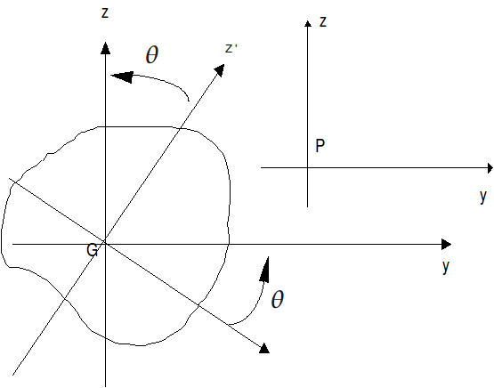
Figure 2: Main and any axes.
The polar geometric moment with respect to the center of gravity is given by: \({I}_{p}={\int }_{s}\mathrm{r²}\mathrm{dS}\) where r is the distance from the element \(\mathrm{dS}\) to the center of gravity [Figure]. We naturally deduce \({I}_{p}={I}_{y}+{I}_{z}\).
The polar geometric moment is used in the calculation of the torsional stiffness of girders with a circular cross section (Saint-Venant twist). For the other shapes of sections, a torsional constant of the same dimension will be defined.
In addition, the geometric moments can be calculated in another coordinate system \((P,y,z)\), of any origin \(P\), different from the center of gravity \(G\) (Huygens formula):
\(\begin{array}{}{I}_{y}^{P}={I}_{y}^{G}+{(\mathrm{GP}\mathrm{.}Z)}^{2}\mathrm{.}S={\int }_{s}{z}^{2}\mathrm{dS}+{(\mathrm{GP}\mathrm{.}Z)}^{2}\mathrm{.}S\\ {I}_{z}^{P}={I}_{z}^{G}+{(\mathrm{GP}\mathrm{.}Y)}^{2}\mathrm{.}S={\int }_{s}{y}^{2}\mathrm{dS}+{(\mathrm{GP}\mathrm{.}Y)}^{2}\mathrm{.}S\\ {I}_{\mathrm{yz}}^{P}={I}_{\mathrm{yz}}^{G}+(\mathrm{GP}\mathrm{.}Y)(\mathrm{GP}\mathrm{.}Z)\mathrm{.}S={\int }_{s}\mathrm{yz}\mathrm{dS}+(\mathrm{GP}\mathrm{.}Y)(\mathrm{GP}\mathrm{.}Z)\mathrm{.}S\end{array}\)
in general, the Huygens formula gives:
\(\begin{array}{}\left[I\right]={\int }_{s}(\text{PG}+\text{GM})\otimes (\text{PG}+\text{GM})\\ \phantom{\left[I\right]}\text{=}{\int }_{s}\text{PG}\otimes \text{PG}+{\int }_{s}\text{GM}\otimes \text{GM}\\ \phantom{\left[I\right]}+2{\int }_{s}\text{PG}\otimes \text{GM}\\ \phantom{\left[I\right]}\text{=}S(\text{PG}\otimes \text{PG})+{\int }_{s}\text{GM}\otimes \text{GM}\end{array}\)
1.1.2. Calculating geometric characteristics using MACR_CARA_POUTRE#
This macro-command allows the determination of the characteristics of a beam cross section from a 2D mesh of the [U4.42.02] section. It allows you to build a table of values, usable in the AFFE_CARA_ELEM command (SECTION: “GENERALE” [U4.42.01]).
Geometric characteristics can be calculated on the full mesh, half mesh with symmetry with respect to \(Y\) or \(Z\), quarter mesh with two symmetries with respect to \(Y\) and to \(Z\) [Figure].
These characteristics are calculated in the table for the entire mesh and for each group of elements in the list specified by the user (case of a network of beams).
The data corresponds to a half or a quarter of the section if the keywords SYME_Y or SYME_Z are present.
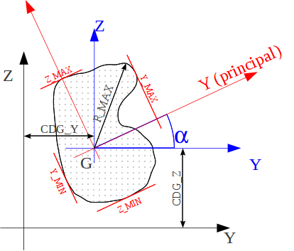
Figure 3 : Definition of geometric characteristics.
The results are grouped into four groups:
In frame \(\mathit{OYZ}\) describing the 2D mesh for the mesh provided by the user
area: A_M
center of gravity position: CDG_Y_M, CDG_Z_M
moments and product of inertia of air, at the center of gravity \(G\) in the GYZ coordinate system: IY_G_M, IZ_G_M, IYZ_G_M
In the same global coordinate system, for the mesh obtained by symmetrization if SYME_Y or SYME_Z:
area: A
center of gravity position: CDG_Y, CDG_Z
moments and product of inertia of air, at the center of gravity \(G\) in the GYZ coordinate system: IY_G, IZ_G, IYZ_G
In the main inertia coordinate system \(\mathrm{Gyz}\). in the right section, whose name corresponds to that used in the description of neutral fiber beam elements \(\mathrm{Gx}\) [U4.24.01].
main moments of inertia of air in frame \(\mathrm{Gyz}\), usable for calculating the flexural stiffness of the beam: IY and IZ
angle of transition from coordinate system \(\mathit{GYZ}\) to the main inertia coordinate system \(\mathrm{Gyz}\): ALPHA
characteristic distances, in relation to the center of gravity \(G\) of the section for maximum stress calculations: Y_ MAX, Y_ MIN, Z_ MAX, Z_ MIN and R_ MAX.
In the global frame of reference, at a point \(P\) provided by the user:
Y_P, Z_P: point for calculating moments of inertia
IY_P, IZ_P, IYZ_P: moments of inertia in the PYZ coordinate system
IY_P, IZ_P: moments of inertia in the Pyz coordinate system.
1.1.3. Calculations made#
The list of commands called by MACR_CARA_POUTRE is shown in document [U4.42.02].
The previous quantities are obtained by calling POST_ELEM, for the option “CARA_GEOM”. In addition, you can add the keywords SYME_Y, SYME_Z, and ORIG_INER which define the point \(P\).
The calculations are performed in POST_ELEM, for the entire mesh, then possibly for each group of elements, as follows:
Loop over the 2D elements (D_ PLAN modeling), with the call of the elementary option “MASS_INER”. We get a CHAM_ELEM with one value per element (1 Gauss point) containing the components:
\({\int }_{\mathrm{élément}}\mathrm{dS},{\int }_{\stackrel{x}{\mathrm{élément}}}\mathrm{dS},{\int }_{\mathrm{élément}}\mathrm{dS}\) \({\int }_{s}\mathrm{x²}\mathrm{dS},{\int }_{s}\mathrm{y²}\mathrm{dS},{\int }_{s}\mathrm{xy}\mathrm{dS}\),
Summation of the previous elementary quantities to obtain: A_M, CDG_Y_M,, CDG_Z_M, IY_G_M, IZ_G_M, IYZ_G_M
Calculation of A, CDG_Y, CDG_Z, IY_G, IZ_G, IYZ_G (taking into account SYME_Y, SYME_Z)
Calculating IY, IZ, ALPHA
If you specify a particular point \(P\) (keyword ORIG_INER), you also calculate the characteristics in the original global coordinate system \(P\): \(\mathit{PYZ}\)
1.1.4. Examples of use: Full rectangle (processed by test SSLL107G)#
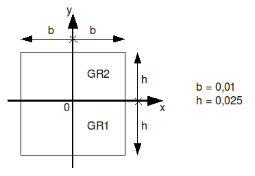
Geometric characteristics obtained
LIEU A_M CDG_Y_M CDG_Z_M IY_G_M IZ_G_M IYZ_G_M

0.000003 1.00E-03 4.24E-18 -3.39E-18 -3.39E-18 2.08E-07 3.33E-08 2.65E-23

GR1 5.00E-04 2.20E-17 -1.25E-02 2.60E-08 1.67E-08 3.97E-23

GR2 5.00E-04 -8.47E-18 1.25E-02 2.60E-08 1.67E-08 5.62E-23


LIEU A CDG_Y CDG_Z IY_G IZ_G IYZ_G IY IZ ALPHA

0.000003 1.00E-03 4.24E-18 -3.39E-18 -3.39E-18 2.08E-07 3.33E-08 2.65E-23 3.33E-08 2.08E-07 9.00E+01

GR1 5.00E-04 2.20E-17 -1.25E-02 2.60E-02 2.60E-08 1.67E-08 3.97E-23 1.67E-08 2.60E-08 9.00E-08 9.00E+01

GR2 5.00E-04 -8.47E-18 1.25E-02 2.60E-08 1.67E-08 5.62E-23 1.67E-08 2.60E-08 9.00E-08 9.00E+01


LIEU Y_P Z_P IY_P IZ_P IYZ_P IY_PRIN_P IZ_PRIN_P

0.000003 0.00E+00 0.00E+00 2.08E-07 3.33E-08 2.65E-23 3.33E-08 2.08E-07

GR1 0.00E+00 0.00E+00 1.04E-07 1.67E-08 -9.79E-23 1.67E-08 1.04E-07

GR2 0.00E+00 0.00E+00 1.04E-07 1.67E-08 3.31E-24 1.67E-08 1.04E-07


LIEU Y_ MAX Z_ MAX Y_ MIN Z_ MIN R_ MAX

0.000003 2.50E-02 1.00E-02 -2.50E-02 -1.00E-02 2.69E-02

GR1 2.50E-02 2.25E-02 -2.50E-02 2.50E-02 2.50E-03 3.36E-02

GR2 2.50E-02 -2.50E-03 -2.50E-03 -2.50E-02 -2.25E-02 3.36E-02


LIEU MX AU AZ AND EZ PCTY PCTZ RT

0.000003 - - - - - - - - - 1.93871E-2

GR1 3.43E-08 1.20E+00 1.20E+00 9.00E-17 -3.97E-18 2.60E-17 -1.25E-02 1.56391E-2

GR2 3.43E-08 1.20E+00 1.20E+00 -4.03E-17 1.19E-16 -1.27E-16 1.25E-02 1.56391E-2
1.2. Special case of rectangular and circular sections#
Geometric characteristics are directly calculated in AFFE_CARA_ELEM based on user data.
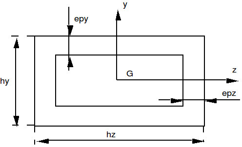
Figure 4 : rectangular section.
In the case of the rectangular beam (Operand SECTION: “RECTANGLE”), the calculation gives:
\({I}_{y}=\frac{1}{12}\left[{h}_{y}{h}_{z}^{3}-({h}_{y}-2{\mathrm{ep}}_{y}){({h}_{z}-{\mathrm{2ep}}_{z})}^{3}\right]\)
\({I}_{z}=\frac{1}{12}\left[{h}_{z}{h}_{y}^{3}-({h}_{z}-2{\mathrm{ep}}_{z}){({h}_{y}-{\mathrm{2ep}}_{y})}^{3}\right]\)
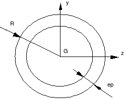
Figure 5 : circular section
For the circular section (Operand SECTION: “CERCLE”), we get:
\({I}_{y}={I}_{z}=\frac{p}{4}\left[{R}^{4}-{(R-\mathrm{ep})}^{4}\right]\) \({I}_{p}=\frac{p}{2}\left[{R}^{4}-{(R-\mathrm{ep})}^{4}\right]\)