1. Reference problem#
1.1. 2D geometry#
The structure is a rectangle made up of two plates of the same material, separated by an interface.
The dimensions of the plate, on which the pressures are applied, are:
\({L}_{X}\mathrm{=}\mathrm{2m}\), \({L}_{Y}\mathrm{=}\mathrm{1,8}m\)
The second plate has the following dimensions:
\({L}_{X}\mathrm{=}\mathrm{2m}\), \({L}_{Y}’\mathrm{=}\mathrm{1,2}m\)
The position of the reference points is:
\(x\) |
|
|
\(A\) |
-1 |
0 |
\(B\) |
1 |
0 |
\(C\) |
1 |
1.8 |
\(D\) |
-1 |
1.8 |
\(O\) |
0 |
0 |
1.2. 3D geometry#
The structure is a rectangular parallelepiped made up of two plates of the same material, separated by an interface.
The dimensions of the top plate, on which the pressures are applied, are:
\({L}_{X}\mathrm{=}\mathrm{2m}\), \({L}_{Y}\mathrm{=}\mathrm{1,8}m\), \({L}_{Z}\mathrm{=}\mathrm{0,01}m\)
The second plate underneath has the following dimensions:
\({L}_{X}\mathrm{=}\mathrm{2m}\), \({L}_{Y}’\mathrm{=}\mathrm{1,2}m\), \({L}_{Z}\mathrm{=}\mathrm{0,01}m\)
The position of the reference points is:
\(x\) |
|
|
||
\(A\) |
-1 |
0 |
0 |
|
\(B\) |
1 |
0 |
0 |
|
\(C\) |
1 |
1.8 |
0 |
|
\(D\) |
-1 |
1.8 |
0 |
|
\(O\) |
0 |
0 |
0 |
|
\(A\text{'}\) |
-1 |
0 |
-0.01 |
|
\(B\text{'}\) |
1 |
0 |
-0.01 |
|
\(C\text{'}\) |
1 |
1.8 |
-0.01 |
|
\(D\text{'}\) |
-1 |
1.8 |
-0.01 |
|
\(O\text{'}\) |
0 |
0 |
0 |
-0.01 |
1.3. Material properties#
Poisson’s ratio: \(0.2\)
Young’s module: \(1.{10}^{10}N/{m}^{2}\)
1.4. Boundary conditions and loads#
The lower plate \((y<0)\) is blocked by an embedding of its lower face.
Plan \(\mathit{ABCD}\) is stuck in the \({e}_{z}\) direction.
In the 3D case, the \((x\mathrm{=}0)\) plane is blocked in the \({e}_{x}\) direction, and in the 2D case, the line \((x\mathrm{=}0)\) is blocked in the \({e}_{x}\) direction.
The upper plate \((y>0)\) is subjected to a distributed horizontal pressure acting on the lateral faces \(P\mathrm{=}\mathrm{\pm }(\mathrm{-}{5.10}^{4}y+{1.10}^{5})N\mathrm{/}{m}^{2}\) (according to the principle of compression). A quadratic tensile displacement is applied to it on the upper face \(d\mathrm{=}\mathrm{-}\mathrm{2,5}{.10}^{\mathrm{-}6}{x}^{2}+{1.10}^{\mathrm{-}5}m\).
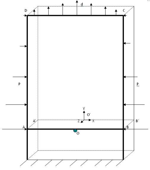
Figure 1: Structure geometry and interface positioning and 3D loads