4. B modeling#
4.1. Characteristics of modeling#
Modeling: C_ PLAN.
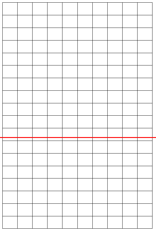
The structure is a healthy rectangle, in which an interface is introduced directly into the command file using the DEFI_FISS_XFEM [U4.82.08] operator. The interface is present at a distance \({L}_{Y}\mathrm{=}\mathrm{1,8}m\) from the top edge of the plate.
4.2. Characteristics of the mesh#
Number of knots: 597
Number of meshes and types: 180 QUAD8 for the plate and 46 SEG3 for the edges.

Figure 4.2‑a: 2D quadrangle mesh and interface position
4.3. Tested sizes and results#
The movements resulting from the operator STAT_NON_LINE are post-processed in order to recover the values at the nodes of the crack from the new mesh.
Identification |
Reference |
Aster |
tolerance |
\(\mathrm{DX}\) at point \(A\) |
1.10-5 |
Analytical |
1.10-12 |
\(\mathrm{DX}\) at point \(B\) |
-1.10-5 |
Analytical |
1.10-12 |
\(\mathrm{DY}\) at point \(A\) |
5,52.10-6 |
Analytical |
1.10-12 |
\(\mathrm{DY}\) at point \(B\) |
5,52.10-6 |
Analytical |
1.10-12 |
\(\mathrm{DY}\) at point \(O\) |
8,02.10-6 |
Analytical |
1.10-12 |
4.4. Comments#
This test validates:
the calculation of the stiffness matrix and the second member vectors (taking into account the pressure distributed over elements with quadratic edges),
subdivision (configuration in the right interface and elements with straight edges),
the X- FEM post-processing of the \(\mathrm{P2}\) elements.