1. Reference problem#
1.1. Geometry#
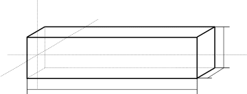
The concrete beam is straight and has a square cross section.
Its dimensions are \(L\mathrm{\times }a\mathrm{\times }a\mathrm{=}3m\mathrm{\times }\mathrm{0,4}m\mathrm{\times }\mathrm{0,4}m\).
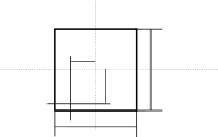
The cable crosses the beam parallel to the middle fiber and is offset from the two main planes. The eccentricities in the directions \(y\) and \(z\) apply respectively
\({e}_{y}=-\mathrm{0,12}m\) and \({e}_{z}=-\mathrm{0,16}m\).
The cross-sectional area of the cable is \({S}_{a}=\mathrm{2,5}{.10}^{-3}{m}^{2}\).

Z
Y
hath
X
hath
L
Z
Ey
Y

Ez
hath
hath
1.2. Material properties#
Concrete material constituting the beam: Young’s modulus \({E}_{b}\mathrm{=}\mathrm{4,5}{.10}^{10}\mathit{Pa}\)
Material: steel constituting the cable: Young’s modulus \({E}_{a}\mathrm{=}\mathrm{1,85}{.10}^{11}\mathit{Pa}\)
The Poisson’s ratio is taken to be equal to 0 for both materials. We therefore cancel the Poisson effects in the \(y\) and \(z\) directions.
Since voltage losses in the cable are neglected, the various parameters used to estimate them are set to 0.
1.3. Boundary conditions and loads#
The nodes of the beam located on face \(x=0\) are blocked in translation in three directions. Among these nodes are the « neighbors » of the left-hand end node of the cable, which is therefore blocked in translation by kinematic relationships. It is therefore not necessary to impose additional boundary conditions at this node, which would be redundant with kinematic relationships and would make it impossible to resolve displacements (singular matrix).
A normal pull force \(({F}_{\mathrm{0 }};\mathrm{0 };0)\) is applied to the right end node of the cable, with \({F}_{0}={10}^{6}N\).