1. Reference problem#
1.1. Geometry#
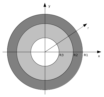
The structure is composed of two concentric circular crowns. The inner radius \({R}_{2}\) of the outer ring is equal to the outer radius of the inner ring (Figure 1.1-1).
The characteristic dimensions of the structure are:
\({R}_{1}\mathrm{=}\mathrm{1,0}m;{R}_{2}\mathrm{=}\mathrm{0,6}m;{R}_{3}\mathrm{=}\mathrm{0,2}m\)

Figure 1.1-1: Structure geometry
1.2. Material properties#
The Young’s modulus and the Poisson’s ratio of the material in the outer ring are given by \({E}_{1}\) and \({\nu }_{1}\) (respectively \({E}_{2}\) and \({\nu }_{2}\) for the inner ring).
1.3. Boundary conditions and loads#
1.3.1. Boundary conditions in the case without rotation#
The outer ring is subjected to a displacement equivalent to the application of pressure \(p\) on its edge (\(r\mathrm{=}{R}_{1}\)) while the edge of the inner ring (\(r\mathrm{=}{R}_{3}\)) is left free of stress.
\(\begin{array}{c}{\xi }_{X}(r)\mathrm{=}f(r)\mathrm{cos}(\mathrm{arctan}(\frac{Y}{X}))\\ {\xi }_{Y}(r)\mathrm{=}f(r)\mathrm{sin}(\mathrm{arctan}(\frac{Y}{X}))\end{array}\)
The function \(f(r)\) of the radial displacement is given as a function of the properties of the materials and the pressure \(p\). In the case of plane deformations (MODELISATION = “D_ PLAN “) we have:
\(\begin{array}{c}f({R}_{1})\mathrm{=}\frac{1+{\nu }_{1}}{{E}_{1}}({A}_{1}(1\mathrm{-}2{\nu }_{1}){R}_{1}+\frac{{B}_{1}}{{R}_{1}})\\ f({R}_{3})\mathrm{=}\frac{1+{\nu }_{2}}{{E}_{2}}({A}_{2}(1\mathrm{-}2{\nu }_{2}){R}_{3}+\frac{{B}_{2}}{{R}_{3}})\end{array}\) eq 1.1
with:
\(\begin{array}{c}{A}_{1}\mathrm{=}\frac{\mathrm{-}p{R}_{1}^{2}+\lambda {R}_{2}^{2}}{{R}_{1}^{2}\mathrm{-}{R}_{2}^{2}};{B}_{1}\mathrm{=}(\mathrm{-}p+\lambda )\frac{{R}_{1}^{2}{R}_{2}^{2}}{{R}_{1}^{2}\mathrm{-}{R}_{2}^{2}}\\ {A}_{2}\mathrm{=}\mathrm{-}\lambda \frac{{R}_{2}^{2}}{{R}_{2}^{2}\mathrm{-}{R}_{3}^{2}};{B}_{2}\mathrm{=}\mathrm{-}\lambda \frac{{R}_{2}^{2}{R}_{3}^{2}}{{R}_{2}^{2}\mathrm{-}{R}_{3}^{2}}\end{array}\) eq 1.2
Where \(\lambda\) is the contact pressure whose analytic expression is:
\(\lambda \mathrm{=}2p(1\mathrm{-}{\nu }_{1})\frac{\frac{{R}_{1}^{2}}{{R}_{1}^{2}\mathrm{-}{R}_{2}^{2}}}{\frac{{R}_{1}^{2}+{R}_{2}^{2}(1\mathrm{-}2{\nu }_{1})}{{R}_{1}^{2}\mathrm{-}{R}_{2}^{2}}+\frac{{E}_{1}}{{E}_{2}}\frac{(1+{\nu }_{1})}{(1+{\nu }_{2})}\frac{{R}_{2}^{2}(1\mathrm{-}2{\nu }_{2})+{R}_{3}^{2}}{{R}_{2}^{2}\mathrm{-}{R}_{3}^{2}}}\) eq. 1.3
Note that in the case of plane deformations the Poisson coefficients do not intervene in the equations, while in the case of plane stresses (MODELISATION = “C_ PLAN “) we have:
\(\begin{array}{c}f({R}_{1})\mathrm{=}\frac{1}{{E}_{1}}({A}_{1}(1\mathrm{-}{\nu }_{1}){R}_{1}+\frac{{B}_{1}(1+{\nu }_{1})}{{R}_{1}})\\ f({R}_{3})\mathrm{=}\frac{1}{{E}_{2}}({A}_{2}(1\mathrm{-}{\nu }_{2}){R}_{3}+\frac{{B}_{2}(1+{\nu }_{2})}{{R}_{3}})\end{array}\) eq 1.4
The expressions for \({A}_{1}\), \({B}_{1}\), \({A}_{2}\), and \({B}_{2}\) are the same as those in Equations 1.2 while the contact pressure is given by:
\(\lambda \mathrm{=}2p\frac{\frac{{R}_{1}^{2}}{{R}_{1}^{2}\mathrm{-}{R}_{2}^{2}}}{\frac{{R}_{1}^{2}(1+{\nu }_{1})+{R}_{2}^{2}(1\mathrm{-}{\nu }_{1})}{{R}_{1}^{2}\mathrm{-}{R}_{2}^{2}}+\frac{{E}_{1}}{{E}_{2}}\frac{{R}_{2}^{2}(1\mathrm{-}{\nu }_{2})+{R}_{3}^{2}(1+{\nu }_{2})}{{R}_{2}^{2}\mathrm{-}{R}_{3}^{2}}}\) eq 1.5
1.3.2. Boundary conditions in the case with rotation#
In addition to the radial displacement, a movement is imposed on the inner surface of the inner ring (\(r\mathrm{=}{R}_{3}\)), causing the latter to rotate. The expression of the displacement must take into account the contraction of the inner ring due to the application of pressure, its new internal radius being \({R}_{3}+f({R}_{3})\):
\(\begin{array}{}{\xi }_{X}(X,Y,i)=({R}_{3}+f({R}_{3}))\mathrm{cos}(\mathrm{arctan}(\frac{Y}{X})+\omega (i))-X\\ {\xi }_{Y}(X,Y,i)=({R}_{3}+f({R}_{3}))\mathrm{sin}(\mathrm{arctan}(\frac{Y}{X})+\omega (i))-Y\\ \omega (i)=\frac{2\pi }{{N}_{t}{N}_{e}}i,i\in \{n\in \mathbb{Z},0\le n\le {N}_{t}\}\end{array}\) eq 1.6
where \({N}_{t}\) is the number of time steps and \({N}_{e}\) is the number of elements along the contact surface. Since a rotation of angle \(\frac{2\pi }{{N}_{e}}\) is imposed, at the last moment we have a configuration similar to the initial configuration but where the inner ring has been offset by one element. In this last configuration, the master and slave meshes of the contact surfaces are again facing each other.