2. Modeling A#
In this modeling, the extended finite element method (\(\text{X-FEM}\)) is used. A radius of geometric enrichment is defined with a number of element layers equal to 3.
2.1. Characteristics of the mesh#
The structure is modelled by a regular mesh composed of \(100\times 100\) QUAD4, respectively along the \(x,y\) axes. The crack is not meshed.
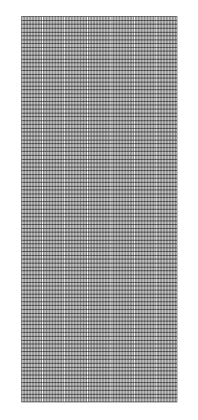
Figure 2.1-1 : mesh of the cracked plate
2.2. Tested sizes and results#
For each value of the angle \(\theta\), we test the value of the stress intensity factors \({K}_{I}\) and \({K}_{\mathrm{II}}\) given by CALC_G (for the two crack backgrounds) as well as those given by K1 and K2 from POST_K1_K2_K3 (for the two crack bottoms).
For method \(G-\mathrm{thêta}\) (command CALC_G), two choices of theta field crowns are tested:
\(\mathrm{C1}\): \({R}_{\mathrm{inf}}=\mathrm{0,1}a\) and \({R}_{\text{sup}}=\mathrm{0,3}a\);
\(\mathrm{C2}\): \({R}_{\mathrm{inf}}=h\) and \({R}_{\text{sup}}=\mathrm{3h}\);
where \(h\) is the characteristic mesh size:
\(h=\sqrt{{(\frac{\mathrm{LX}}{\mathrm{NX}})}^{2}+{(\frac{\mathrm{LY}}{\mathrm{NY}})}^{2}}\)
For the method by extrapolation of movement jumps (POST_K1_K2_K3), the maximum curvilinear abscissa is equal to \(\mathrm{0,3}a\).
2.2.1. Results for thêta= 0°#
Identification |
Reference |
Tolerance |
CALC_G |
||
C1 + background1: K1 |
2.5725 105 |
|
C1 + background2: K1 |
2.5725 105 |
|
C1 + background1: K2 |
0 |
257 |
C1 + background2: K2 |
0 |
257 |
C1 + background1: G |
0.29 |
|
C1 + background2: G |
0.29 |
|
C2 + background1: K1 |
2.5725 105 |
|
C2 + background2: K1 |
2.5725 105 |
|
C2 + background1: K2 |
0 |
257 |
C2 + background2: K2 |
0 |
257 |
C2 + background1: G |
0.29 |
|
C2 + background2: G |
0.29 |
|
POST_K1_K2_K3 |
||
background 1: K1 |
2.5725 105 |
|
background 2: K1 |
2.5725 105 |
|
background 1: K2 |
0 |
257 |
background 2: K2 |
0 |
257 |
The zero values of \({K}_{2}\) are tested in absolute terms with a tolerance equal to \({K}_{1}^{\mathit{ref}}\mathrm{/}1000\).
2.2.2. Results for thêta= 15°#
Identification |
Reference |
CALC_G |
|
C1 + background1: K1 |
2.4001 105 |
C1 + background2: K1 |
2.4001 105 |
C1 + background1: K2 |
6.4313 104 |
C1 + background2: K2 |
6.4313 104 |
C2 + background1: K1 |
2.4001 105 |
C2 + background2: K1 |
2.4001 105 |
C2 + background1: K2 |
6.4313 104 |
C2 + background2: K2 |
6.4313 104 |
POST_K1_K2_K3 |
|
background1: K1 |
2.4001.105 |
background 2: K1 |
2 400 1 105 |
background 1: K2 |
6, 4313 104 |
background 2: K2 |
6, 4313 104 |
2.2.3. Results for thêta= 30°#
Identification |
Reference |
CALC_G |
|
C1 + background1: K1 |
1.9294 105 |
C1 + background2: K1 |
1.9294 105 |
C1 + background1: K2 |
1,139 105 |
C1 + background2: K2 |
1,139 105 |
C2 + background1: K1 |
1.9294 105 |
C2 + background2: K1 |
1.9294 105 |
C2 + background1: K2 |
1,139 105 |
C2 + background2: K2 |
1,139 105 |
POST_K1_K2_K3 |
|
background1: K1 |
1.9294 105 |
background 2: K1 |
1,9294 105 |
background 1: K2 |
1,139 105 |
background 2: K2 |
1,139 105 |
2.2.4. Results for thêta= 45°#
Identification |
Reference |
CALC_G |
|
C1 + background1: K1 |
1.2863 105 |
C1 + background2: K1 |
1.2863 105 |
C1 + background1: K2 |
1.2863 105 |
C1 + background2: K2 |
1.2863 105 |
C2 + background1: K1 |
1.2863 105 |
C2 + background2: K1 |
1.2863 105 |
C2 + background1: K2 |
1.2863 105 |
C2 + background2: K2 |
1.2863 105 |
POST_K1_K2_K3 |
|
background 1: K1 |
1, 2 863 105 |
background 2: K1 |
1, 2 863 105 |
background 1: K2 |
1, 2863 105 |
background 2: K2 |
1, 2863 105 |
2.2.5. Results for thêta= 60°#
Identification |
Reference |
CALC_G |
|
C1 + background1: K1 |
6.4313 104 |
C1 + background2: K1 |
6.4313 104 |
C1 + background1: K2 |
1,140 105 |
C1 + background2: K2 |
1,140 105 |
C2 + background1: K1 |
6.4313 104 |
C2 + background2: K1 |
6.4313 104 |
C2 + background1: K2 |
1,140 105 |
C2 + background2: K2 |
1,140 105 |
POST_K1_K2_K3 |
|
background 1: K1 |
6, 43 13 104 |
background 2: K1 |
6, 43 13 104 |
background 1: K2 |
1,140 105 |
background 2: K2 |
1,140 105 |
2.3. Additional results#
Other \(\theta\) angle values have been tested elsewhere, without being part of this test. They are carried over to Figure 2.3-1.
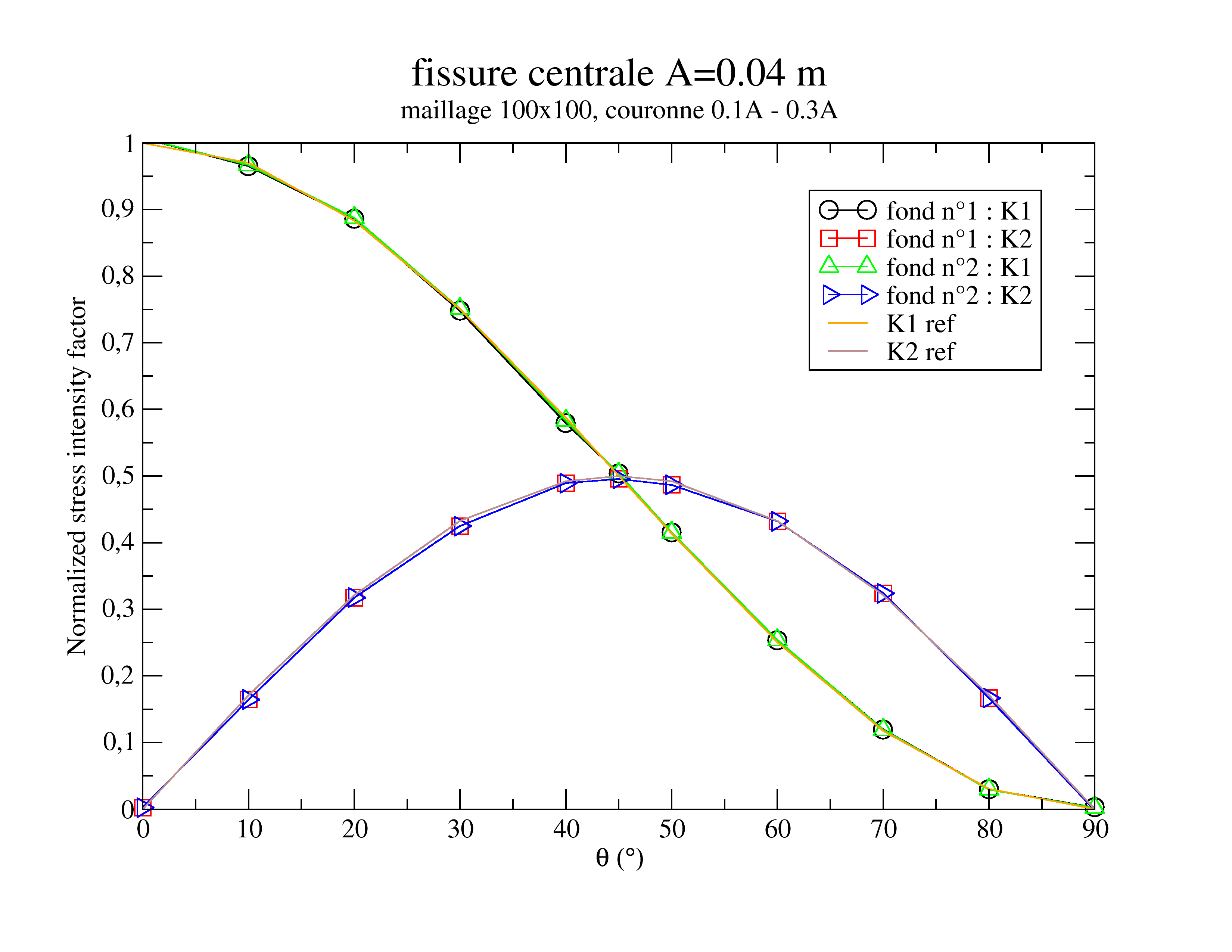
Figure 2.3-1 : stress intensity factors normalized by \({K}_{I}\) (theta= 0°) obtained by CALC_G for the crown \(\mathrm{C1}\)
As an illustration, Figure 2.3-2 shows a view of the deformation of the plate for an angle \(\theta =45°\).
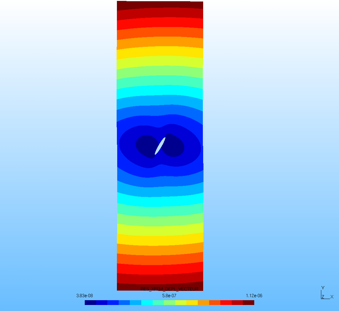
Figure 2.3-2 : deformed for theta= 45°