1. Reference problem#
1.1. Model description#
The spinning foundation model consists of a rigid foundation with a width \(B\) equal to \(2m\) placed on a half-plane representing a porous elastoplastic soil. The foundation is considered to be infinitely long, so the problem can be reduced to a vertical plane (\(\mathrm{2D}\)) containing a section of the foundation (Figure 1). A monotonous vertical displacement directed downwards is imposed on the foundation, and the evolution of the behavior of the soil located under it is observed. Since the problem also has a symmetry with respect to the vertical plane dividing the foundation along its length into two equal parts, we represent only one half of the problem. The ground is thus represented by a square with a side of \(10m\), large enough not to disturb the evolution of the behavior of the soil around the foundation (hypothesis of the infinite half-plane for the ground).
The behavior of the soil is modelled by an elastoplastic law of the Cam-Clay type. The presence of a fluid (water) in saturated condition is also assumed (hydro-mechanical coupling).
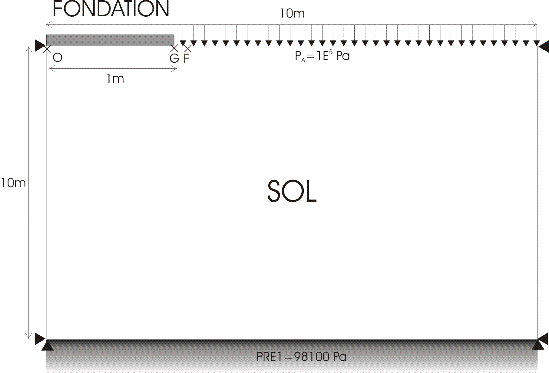

Figure 1: floating foundation model.
1.2. Boundary conditions and initial conditions#
The mechanical boundary conditions are:
\(\mathit{Ux}\mathrm{=}0\) on the lateral edges (horizontal symmetry);
\(\mathit{Uy}\mathrm{=}0\) on the bottom edge (vertical symmetry far enough away from the foundation);
an imposed pressure \({P}_{A}\mathrm{=}{1.E}^{+5}\mathit{Pa}\) (atmospheric pressure) on the upper edge, assumed to be in the open air;
The hydraulic conditions are:
Interstitial pressure \(\mathit{PRE1}\mathrm{=}98100\mathit{Pa}\) on the lower edge (downward drainage).
It should be noted that the absence of explicit boundary conditions is equivalent for hydraulics to impose a zero flow on the edges (non-drainage condition).
The initial conditions in the soil are:
in the case without water * (no hydromechanical coupling) : \({\sigma }_{y}={\rho }_{S}\mathrm{.}g\mathrm{.}(h-y)+{P}_{A}\) \({\sigma }_{x}={K}_{0}\mathrm{.}({\sigma }_{y}-{P}_{A})+{P}_{A}\)
in the case with water (with hydromechanical coupling) : \({\sigma }_{y}={\rho }_{h}\mathrm{.}g\mathrm{.}(h-y)+{P}_{A}\) \({\sigma }_{x}={K}_{0}\mathrm{.}({\sigma }_{y}-{P}_{A})+{P}_{A}\) \(\mathrm{PRE1}={\rho }_{e}\mathrm{.}g\mathrm{.}(h-y)\)
\({\rho }_{S}\), \({\rho }_{e}\), and \({\rho }_{h}={\rho }_{S}+\mathrm{n.}{\rho }_{e}\) represent the densities of soil, fluid, and homogenized, respectively; \(n\) represents the porosity of the soil; \(h\) represents the thickness of the soil domain (or the dimension of the free surface), with \(h\mathrm{=}10m\); \({P}_{A}\) represents the fixed part of the initial stress in the soil, equal to the pressure atmospheric \({1.E}^{+5}\mathit{Pa}\); \({K}_{0}\) represents the land thrust coefficient, here equal to 1.
1.3. Material properties#
The anelastic parameters of the Cam-Clay elastoplastic law, cf. [R7.01.14], are:
porosity: \(n\mathrm{=}0.5\) (corresponds to an initial void index \({e}_{0}\mathrm{=}\frac{n}{1\mathrm{-}n}\mathrm{=}1\));
the elastic compressibility coefficient: \(\kappa =0.05\) (elastic slope in the \([e,\mathrm{ln}(P)]\) plane);
the plastic compressibility coefficient: \(\lambda =0.2\) (plastic slope in the \([e,\mathrm{ln}(P)]\) plane);
the slope of the critical state line: \(M=1.02\) (corresponds to an angle of friction of 25.85°);
critical pressure: \({P}_{\mathit{CR}}={P}_{\mathit{CO}}/2=\mathit{trace}(\mathrm{\sigma })/6={\sigma }_{\mathit{xx}}/3+{\sigma }_{\mathit{yy}}/6\);
The elastic parameters of the soil are:
the density of the grains: \({\rho }_{S}\mathrm{=}1900\mathit{kg}\mathrm{/}{m}^{3}\);
Poisson’s ratio: \(\nu \mathrm{=}0.3\);
Young’s modulus [1] _
: \(E=10\mathit{MPa}\);
the parameters used to control traction: \({K}^{\mathit{cam}}\mathrm{=}\mathit{Ptrac}\mathrm{=}0\).
Finally, the hydraulic parameters are:
the density of water: \({\rho }_{e}\mathrm{=}1000\mathit{kg}\mathrm{/}{m}^{3}\);
viscosity: \(\nu \mathrm{=}0.001\);
intrinsic permeability [2] _
: \({K}^{\text{int}}=1.0\phantom{\rule{2em}{0ex}}{10}^{-12}{m}^{3}/\mathit{kg}/s\);
the coefficient of compressibility of water: \({K}_{e}\mathrm{=}{1.E}^{+10}\);
1.4. Loads#
The loads are as follows:
gravity \(g\mathrm{=}9.81m\mathrm{/}{s}^{2}\), directed downwards;
a vertical downward movement imposed on the foundation, varying linearly from \(0\) to \({D}_{Y}\mathrm{=}\mathrm{-}0.05m\) between \({t}_{0}\mathrm{=}0s\) and \({t}_{1}=1.0\phantom{\rule{2em}{0ex}}{10}^{+7}s\).
If we consider a time step between \(1.0\phantom{\rule{2em}{0ex}}{10}^{+5}s\) and \(1.0\phantom{\rule{2em}{0ex}}{10}^{+6}s\), we obtain a characteristic fluid diffusion distance between each time step between \(1m\) and \(10m\). Compared to the characteristic size of the foundation (\(2m\)), it can be considered that steady state is reached at each time step.
1.5. Results#
The solutions are post-processed at points \(O\), \(G\) located directly under the foundation and \(F\), in terms of loading trajectories in the stress plane \((P’,Q)\). We are also interested in the evolution of the resultant of the vertical force over the width \(B\) of the foundation, as a function of its depression. The solutions obtained by Code_Aster are compared to those calculated by FLAC.