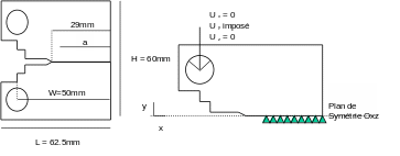
1. Reference problem#
1.1. Geometry#

Uy = 0

Consider a test tube \(\mathrm{CT25}\) with a ligament length: \(a=27.5\mathrm{mm}\) (\(a/W=0.55\)). Along the \(z\) axis, the thickness is \(e=1\mathrm{mm}\). Test piece \(\mathrm{CT25}\) is modelled in plane deformations. For reasons of symmetry, one half of it is represented in \(\mathrm{2D}\).
1.2. Material properties#
Young’s modulus: 214100 \(\mathrm{Mpa}\)
Poisson’s ratio: \(\nu =0.3\). The traction curve used is shown in the following table:
\(\epsilon\) |
|
0.003439678 |
740.6632663 |
0.004628373 |
842.148772 |
0.00607988 |
876.3117064 |
0.007654628 |
895.2063119 |
0.010417548 |
911.0718694 |
0.014178015 |
925.022448 |
0.017543214 |
935.2135771 |
0.021942493 |
945.6948965 |
0.027416704 |
960.732311 |
0.033866984 |
975.8041996 |
0.040205805 |
988.2450325 |
0.046616375 |
1000.143035 |
0.052903597 |
1010.004051 |
0.058235889 |
1017.5664 |
Table 1.1
1.3. Boundary conditions and loads#
The load is of the displacement type imposed at a point located in the center of the pin, which is modelled by four undeformable angular sectors. With half of the test piece modelled, a symmetry condition is applied to the ligament (\(y=0\)).