4. B modeling#
4.1. Characteristics of modeling#
This modeling is two-dimensional, in plane deformations. An initial CT mesh is used. The crack is modelled by a notch with a radius of 100 microns, with a moderately fine mesh. The initial mesh consists of 2937 nodes and 1377 elements. It is visible in Figures and.
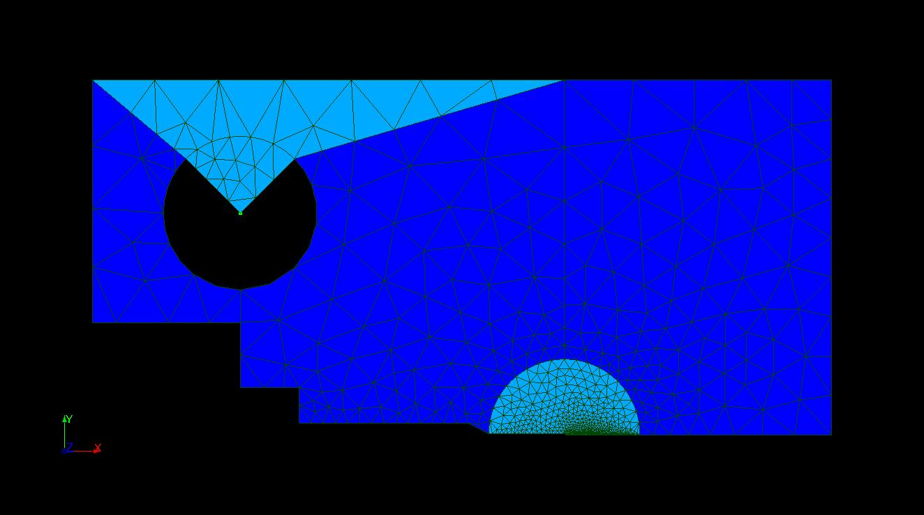
Figure 4.1: Overview of the initial mesh.
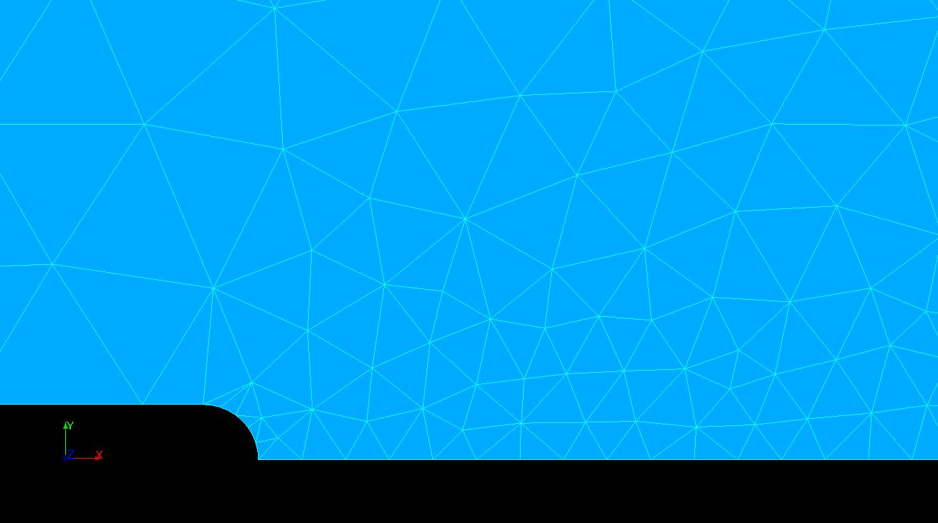
Figure 4.2: Zoom in on the initial mesh notch.
The mesh is then refined with the RAFF_GP command on an area of 10 chips of 20 microns (i.e. on 0.2 mm). Figure shows the mesh finally obtained, comprising 4920 nodes for 1377 elements.
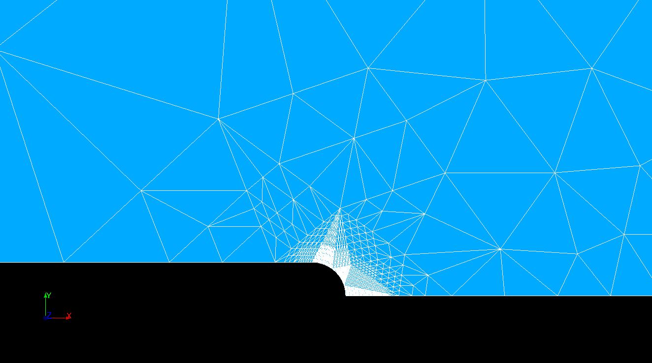
Figure 4.3: Zoom in on the refined mesh notch.
4.2. Tested sizes and results#
With operator CALC_GP and automatic definition of chips by the mesh:
Identification |
Aster Reference |
Tolerance (%) |
\({G}_{P}\) at time 40 at chip 3 |
0.717171792604019 |
0.010 |
The differences noted between the various calculation possibilities are due to the choice of the elastic free energy used either in the case of an explicit mesh of the chips or in the case of free meshing, respectively \({W}_{\mathit{elas}}^{\mathit{traction}}(\Delta S)\) and \({W}_{\mathit{elas}}(\Delta S)\). In the case of the explicit mesh of the chips (\({W}_{\mathit{elas}}^{\mathit{traction}}(\Delta S)\)), where the participation of spherical compression and compression in each specific direction of deformation is removed, the elastic energy will be modified into an elastic tensile energy and by definition \({W}_{\mathit{elas}}^{\mathit{traction}}(\Delta S)<{W}_{\mathit{elas}}(\Delta S)\).