5. C modeling#
5.1. Characteristics of modeling#
The beam is modeled by DKTG elements. 16 elements are used in the longitudinal direction \(X\) and only one in the transverse direction \(Z\).
Reinforced concrete is modelled by behavior law GLRC_DM. The parameters of the law of behavior GLRC_DM are obtained using the DEFI_GLRC macrocommand. The material data used is defined in 1.2. For the reinforcement layers of model GLRC, a reinforcement section \(\mathit{OMX}=\mathit{OMY}=\mathrm{4,27E-3}\mathit{m²}/m\) and the eccentricity \(\mathit{RX}=\mathit{RY}=\mathrm{0,872}\) are defined.
5.2. Tested sizes and results#
The values are based on experimental results (SOURCE_EXTERNE). The arrow is that of the center of the beam, the local results (deformations) are those of the Gauss point of an element of the reinforcement grid (the closest to the middle of the beam).
Since law GLRC_DM is a homogenized reinforced concrete law, the stresses and deformations of the concrete or reinforcements included in the law are not accessible.
Press reaction on center of edge A:
Arrow (m) |
Height |
Location |
Reference type |
Reference |
Tolerance |
||
3.00E-03 |
|
DY |
DY |
Group:A |
SOURCE_EXTERNE |
2.95780E+04 |
0.04 |
0.50E-02 |
|
DY |
DY |
Group:A |
SOURCE_EXTERNE |
4.02560E+04 |
0.07 |
0.7E-02 |
|
DY |
DY |
Group:A |
SOURCE_EXTERNE |
4.98640E+04 |
0.08 |
1.1E-02 |
|
DY |
DY |
Group:A |
SOURCE_EXTERNE |
6.97240E+04 |
0.11 |
1.6E-02 |
|
DY |
DY |
Group:A |
SOURCE_EXTERNE |
8.95840E+04 |
0.08 |
1.9E-02 |
|
DY |
DY |
Group:A |
SOURCE_EXTERNE |
9.9940E+04 |
0.05 |
5.0E-02 |
|
DY |
DY |
Group:A |
SOURCE_EXTERNE |
1.1768E+05 |
0.91 |
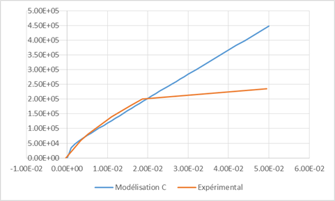
Figure 5.2-a : Support reaction as a function of the arrow in the centre