1. General characteristics#
1.1. Geometry#
The three-point bending beam studied is 5m long. Its section is 0.2x0.5m. Its geometry as well as the positioning of the steels that constitute it are defined on the.
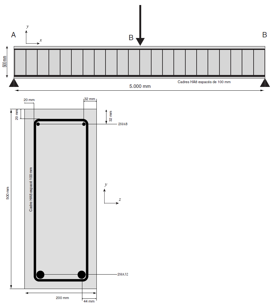
Figure 1.1-a: plane of the beam.
1.2. Material properties#
Concrete:
Young’s module: \(E\mathrm{=}37272\mathit{MPa}\)
Poisson’s ratio: \(\nu =0.2\)
Tensile elasticity threshold: \({\sigma }_{\mathrm{ft}}=3.9\mathrm{MPa}\)
Threshold of elasticity in compression: \({\sigma }_{\mathrm{fc}}=38.3\mathrm{MPa}\)
Threshold of elastic deformation under compression: \({\varepsilon }_{\mathrm{fc}}={\mathrm{2.0.10}}^{-3}\)
Cracking energy \({G}_{f}^{1}\mathrm{=}110J\mathrm{/}\mathit{m²}\)
Steel:
Young’s module: \(E=200000\mathrm{MPa}\)
Poisson’s ratio: \(\nu =0.33\)
Elastic limit: \({\sigma }_{e}\mathrm{=}400\mathit{MPa}\)
Tangent module (plastic slope) \({E}_{T}\mathrm{=}3280\mathit{MPa}\)
AND
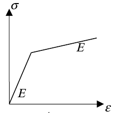
Figure 1.2-a: c stress curve — steel deformation
1.3. Boundary conditions and loads#
Simple press in \(B\): \(\mathit{DY}=0\).
Double press in \(A\): \(\mathit{DX}=\mathit{DY}=\mathit{DZ}=0\) as well as \(\mathit{DRX}=\mathit{DRY}=0\).
Quasi-static loading: monotonic downward displacement \(\mathit{DY}\) applied halfway through \(C\) (3-point flexure test), according to a linear function of time:
\(t\) |
|
\(\mathrm{0,0}\) |
|
\(\mathrm{3,0}\) |
|
\(\mathrm{5,0}\) |
|
The final displacement applied for modeling A is \(\mathrm{-}\mathrm{3,0}\mathit{cm}\).
For the D modeling, the imposed displacement is done according to \(\mathit{DZ}\).
Note: transverse reinforcements are not taken into account in the calculations.