1. Description#
1.1. Geometry#
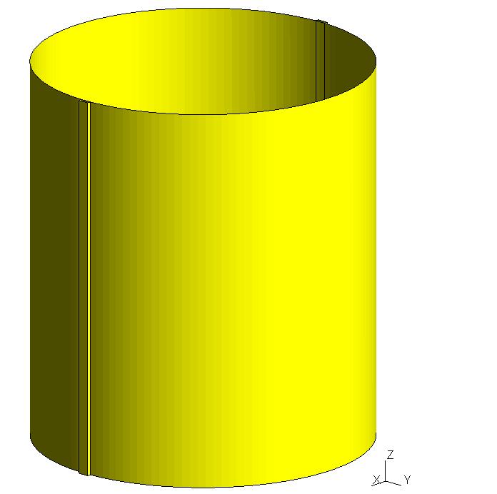
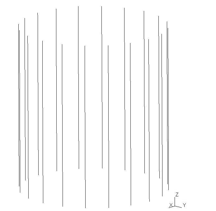
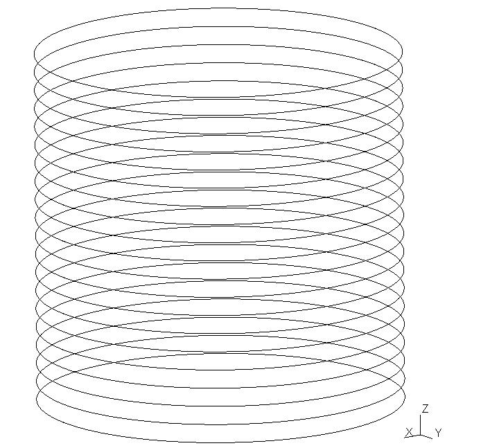
The study model is a cylindrical envelope with an average radius \(R=21.9m\), a height \(H=49.6m\) and a thickness \(t=0.6m\). The cable anchors on the sides of the cylinder have a length of \(L=1.5m\) and a width of \(l=0.5m\). As for the cables, they are positioned on the outer skin of the cylinder. They are then offset by a distance \(e=0.25m\). The model is composed of \(20\) horizontal cables and \(20\) vertical cables. The figures below show the various components of the study model.
|
|
Cylinder |
Vertical cables |
|
|
Horizontal cables |
Study model |
1.2. Meshing#
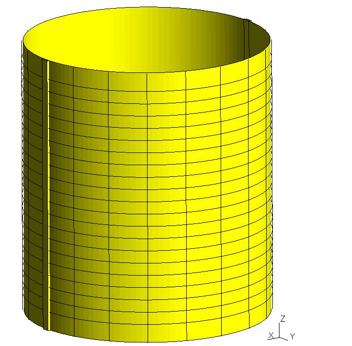
The cables are meshed with SEG2 meshes. The cylinder and the cable anchors are meshed with QUAD4 meshes. The discretization in space for the various components is at most \(f=1.0m\). The following figures represent the meshes for the various parts of the model.
|
|
Horizontal cable meshing |
Vertical cable meshing |
|
|
Cylinder mesh and anchors |
|
1.3. Material properties#
The properties of concrete for the cylinder and the anchors and of steel for the pretension cables are listed in the following table.
Material |
Concrete |
Steel |
Young Module |
\(4\times {10}^{10}\mathit{Pa}\) |
|
Fish Coefficient |
\(0.2\) |
|
Density |
\(2500\mathit{kg}/{m}^{3}\) |
|
Elastic limit stress |
\(n/a\) |
|
1.4. Boundary conditions and loads#
The cylinder and the anchors are embedded at the top and bottom.
Initially, a voltage equal to \(3.75\times {10}^{6}N\) is imposed in the cables. The nodes at the ends of vertical and horizontal cables are considered « active. »
In a second step, the cylinder is subjected to an internal pressure that increases over time (from \({P}_{i}=0\mathit{Pa}\) to \({P}_{f}=1\mathit{kbar}\) in \(\Delta t\mathrm{=}1\mathit{ms}\)). This load is shown in the following graph.
1.5. Main stages of testing#
Macro-control DEFI_CABLE_BP is used to obtain the kinematic relationships between the cylinder and the cables as well as the load related to the tension in the cables.
The macro-command CALC_PRECONT is then launched to prestress the structure using the tensions of the given cables.
The result of this prestress is given in initial state to the macro-command CALC_EUROPLEXUS in order to calculate the mechanical response of the prestressed cylinder to the internal pressure load.
To validate the results from CALC_EUROPLEXUS, we do the same calculation with the DYNA_NON_LINE operator.
From the two concept results obtained, the following are extracted:
the evolution as a function of the time of movement on the reference point located halfway up the cylinder, i.e. in \((\mathrm{0,}R,H/2)\), noted \({N}_{\mathit{ref}}^{\mathit{cyl}}\).
the resulting forces of membrane \(\mathit{Nxx}\) and \(\mathit{Nyy}\), at three different times in a cylinder cell having a node in common with the reference node of the cylinder, noted \({M}_{\mathit{ref}}^{\mathit{cyl}}\).
the normal force in an element of the horizontal cable located closest to halfway up the cylinder and farthest from the anchors, noted \({\mathit{EL}}_{\mathit{ref}}^{\mathit{câb}}\).