2. Reference solution#
2.1. Calculation method used for the reference solution#
The elastic relationships, connecting membrane forces \(N\) and bending forces \(M\) to membrane strains \(\varepsilon\) and curvatures \(\kappa\) and taking into account two symmetric grids, are written:
\(N\mathrm{=}(\frac{{E}_{b}h}{1\mathrm{-}{\nu }_{b}^{2}}\left[\begin{array}{ccc}1& {\nu }_{b}& 0\\ {\nu }_{b}& 1& 0\\ 0& 0& \frac{1\mathrm{-}{\nu }_{b}}{2}\end{array}\right]+2{E}_{a}\left[\begin{array}{ccc}{a}_{x}& 0& 0\\ 0& {a}_{y}& 0\\ 0& 0& 0\end{array}\right])\varepsilon\)
\(M\mathrm{=}(\frac{{E}_{b}{h}^{3}}{12(1\mathrm{-}{\nu }_{b}^{2})}\left[\begin{array}{ccc}1& {\nu }_{b}& 0\\ {\nu }_{b}& 1& 0\\ 0& 0& \frac{1\mathrm{-}{\nu }_{b}}{2}\end{array}\right]+2{E}_{a}{e}_{z}^{2}\left[\begin{array}{ccc}{a}_{x}& 0& 0\\ 0& {a}_{y}& 0\\ 0& 0& 0\end{array}\right])\kappa\)
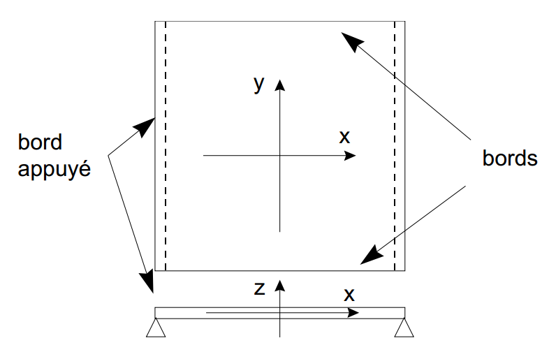
In the case of a beam configuration, a Poisson’s ratio equal to 0 is assigned to the concrete to cancel out any deflection in the perpendicular direction. Two opposite edges of the slab are simply pressed, with two others remaining free:
|
The equivalent bending stiffness that takes steels into account is: \({(\mathit{EI})}_{\mathit{éq}}\mathrm{=}\frac{{E}_{b}l{h}^{3}}{12}+2{E}_{a}{a}_{x}l{e}_{z}^{2}\), or here: \({(\mathit{EI})}_{\mathit{éq}}\mathrm{=}10.111{\mathit{MNm}}^{2}\). |
The elastic solution is calculated in beam theory for an equivalent pressure value \(p\text{'}=\mathrm{pl}\). The values of the moments in the « plate » configuration are obtained by division by the width of the slab \(l\).
Size in the center |
Expression |
Center arrow under surface pressure |
\(w(l\mathrm{/}2)\mathrm{=}\frac{5p\text{'}{l}^{4}}{384{(\mathit{EI})}_{\mathit{éq}}}\) |
Curvature |
\({\kappa }_{\mathit{xx}}(l\mathrm{/}2)\mathrm{=}\frac{p\text{'}{l}^{2}}{8{(\mathit{EI})}_{\mathit{éq}}}\) |
Deformation |
\({\varepsilon }_{\mathit{xx}}\mathrm{=}{\kappa }_{\mathit{xx}}\frac{h}{2}\) |
Global moment (in addition) |
\(M(l\mathrm{/}2)\mathrm{=}p\text{'}{l}^{2}\mathrm{/}8\) |
Global moment (in plate) |
\(M(l\mathrm{/}2)\mathrm{=}p{l}^{2}\mathrm{/}8\) |
2.2. Benchmark results#
For A and B models in which we validate the GLRC_DAMA law with the DKTG elements:
Arrow in the center under surface pressure: \(w=\mathrm{2,433}\mathrm{.}{10}^{-4}m\)
Curvature: \(k=\mathrm{7,210}\mathrm{.}{10}^{-4}{m}^{-1}\)
Deformity: \({\epsilon }_{\mathit{xx}}=-0.4326\mathrm{.}{10}^{-4}\) on the lower skin
Global moment (in addition): \(M=7290\mathit{Nm}\)
Global moment (in plate): \(M=4050\mathit{Nm}/\mathit{ml}\)
For C and D models in which we validate the ELAS law with the Q4GG elements:
Arrow in the center under surface pressure: \(w=\mathrm{2,658}\mathrm{.}{10}^{-4}m\)
Curvature: \(k=\mathrm{7,878}\mathrm{.}{10}^{-4}{m}^{-1}\)
Deformity: \({\epsilon }_{\mathit{xx}}=-0.47269\mathrm{.}{10}^{-4}\) on the lower skin
Global moment (in addition): \(M=7290\mathrm{Nm}\)
Global moment (in plate): \(M=4050\mathrm{Nm}/\mathrm{ml}\)
2.3. Uncertainty about the solution#
Analytical solution.
2.4. Bibliographical reference#
[1] KOECHLIN P., MOULIN S., « Global behavior model of reinforced concrete plates under dynamic flexural loading: Law GLRC « , Note EDF /R &D/ AMA HT-62/01/028A.