3. Modeling A#
3.1. Characteristics of modeling#
Shell element DST (modeling a quarter of a plate).
The user coordinate system is confused with the orthotropy coordinate system.
C
D
A
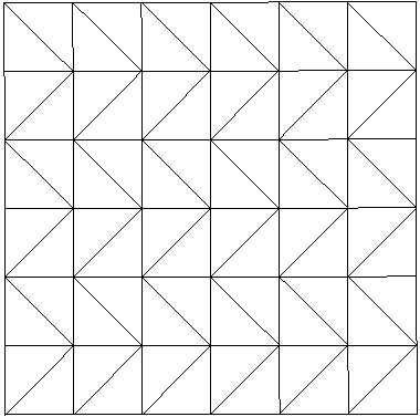
B
Boundary conditions: |
DDL_IMPO |
(GROUP_NO =”AB”, DZ=0., DRY =0.) |
|
(GROUP_NO =”BC”, DX=0., DRY =0.) |
|
(GROUP_NO =”CD”, DY=0., DRX =0.) |
|
(GROUP_NO =”DA”, DZ=0., DRX =0.) |
|
Point C |
mesh: 72 |
3.2. Characteristics of the mesh#
Number of knots: 56
Number of meshes and types: 72 TRIA3
3.3. Tested values#
Point C |
Identification |
Reference |
Aster |
% Difference |
|
\({\sigma }_{x}\) on lower layer 3 |
4.7100E+01 |
4.7662E+01 |
1.194 |
||
\({\sigma }_{x}\) on top layer 3 |
5.8800E+01 |
5.9577E+01 |
1.323 |
||
Constraints |
\({\sigma }_{x}\) on lower layer 2 |
—4.7100E+01 |
—4.7662E+01 |
1.194 |
|
\({\sigma }_{x}\) on top layer 2 |
4.7100E+01 |
4.7662E+01 |
1.194 |
||
\({\sigma }_{x}\) on lower layer 1 |
—5.8800E+01 |
—5.9577E+01 |
1.323 |
||
\({\sigma }_{x}\) on top layer 1 |
—4.7100E+01 |
—4.7662E+01 |
1.194 |
||
\(\mathrm{DX}\) |
0.0 |
0.0 |
0.0 |
||
Displacement |
\(\mathrm{DY}\) |
0.0 |
0.0 |
0.0 |
0.0 |
\(\mathrm{DZ}\) |
4.1920E+01 |
4.1851E+01 |
—0.163 |
3.4. Contents of the results file#
Values at the displacement observation point and constraints \({\sigma }_{x}\).