1. Reference problem#
1.1. Geometry#
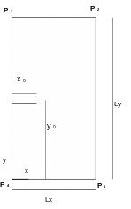
The 2D structure is a rectangular plate (\(\mathrm{LX}=10m\), \(\mathrm{LY}=30m\)), with an through crack [Figure 1.1-a]. The length of the initial crack is \(a=5m\).
We call the « bottom line » the line in \(y=0\) and « top line » the line in \(y=\mathrm{Ly}\).

Figure 1.1-a: geometry of the cracked plate
The nodes marked \(\mathrm{P1}\) and \(\mathrm{P4}\) on the Figure 1.1-a are used to impose boundary conditions, which are explained in paragraph [§ 1.3].
1.2. Material properties#
Young’s module: \(E=205{10}^{9}\mathrm{Pa}\)
Poisson’s ratio: \(\nu =0\)
1.3. Boundary conditions and loads#
Charging consists of applying a force distributed over the lower and upper lines \(p=106\mathrm{Pa}\) and in the direction of the external normal to the surface.
In order to block rigid modes, we block the movements of the nodes \({P}_{1}\), \({P}_{2}\), \({P}_{3}\) and \({P}_{4}\) as follows:
\({\mathrm{DY}}^{\mathrm{P4}}={\mathrm{DY}}^{\mathrm{P1}}=0\);
\({\mathrm{DX}}^{\mathrm{P4}}=0\).