1. Reference problem#
1.1. Geometry#
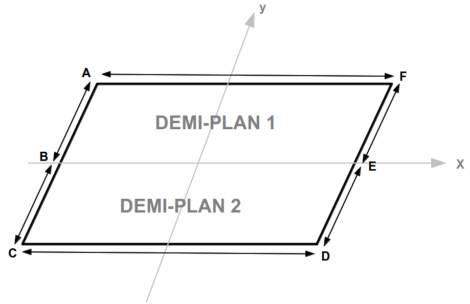
Figure 1.1 Problem geometry
Length: \(L=20\mathit{cm}\)
Width: \(l=20\mathit{cm}\)
\(\mathit{AC}=\mathit{CD}\)
1.2. Material properties#
Material for half plane 1:
Young’s module |
\(E=2\times {10}^{12}\mathit{Pa}\) |
Poisson’s Ratio |
\(\nu =0.3\) |
Material for half plane 2:
Young’s Module |
A, D Modeling: \(E=8\times {10}^{12}\mathit{Pa}\) B, E modeling: \(E=2\times {10}^{12}\mathit{Pa}\) C, F modeling: \(E=5\times {10}^{11}\mathit{Pa}\) |
Poisson’s Ratio |
\(\nu =0.3\) |
1.3. Boundary conditions and loads#
For models A, B and C:
Imposed displacement:
Embedding sides \(\mathit{AB}\), \(\mathit{BC}\) |
|
Embedding point B: |
\(\mathit{DY}=0\) |
Uniform connection on the side: \(\mathit{DE}\) |
|
Uniform connection on the side: \(\mathit{EF}\) |
|
For D, E, and F models:
Imposed displacement:
Embedding point B: |
\(\mathit{DX}=0\), \(\mathit{DY}=0\) |
Embedding point E: |
\(\mathit{DY}=0\) |
For A, B, C, D, E, and F models:
Imposed loading:
Force contour on the side \(\mathit{CD}\) |
|
Force contour on the side \(\mathit{FA}\) |
|
1.4. Crack size#
\(c\): characteristic length of the horizontal crack.
\(a\): characteristic length of the deflected crack a \(45°\).
\(c\) |
|
|
A, B, and C modeling |
\(\mathrm{0,02}\) |
|
D, E, and F modeling |
\(\mathrm{0,02}\) |
|