1. Reference problem#
1.1. Geometry#
Software MISS3D uses the frequency coupling method to take into account soil-structure interaction. This method, based on dynamic substructuring, consists in dividing the field of study into three sub-areas:
the ground,
the foundation,
the building.
The floor
The ground corresponds to the 10-horizontal layer profile shown on [Figure 1.1-a] below:
++—————————————————————————————————————————-+ || | ++—————————————————————————————————————————-+ || | ++ .. image:: images/10000000000001FE0000013A7A6A3196310B57A9.jpg + || :width: 4.039in | ++ :height: 3.0638in + || | ++ + || | ++—————————————————————————————————————————-+
Figure 1.1-a: Configuration of buildings juxtaposed [bib1]
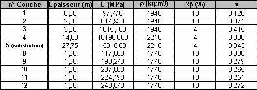
Table 1.1-a: soil in buried foundation configuration [bia1]
The foundation
The surface foundation of the 2 buildings is represented on the [Figure 1.1-b] below. Two surface models of the foundation complete two skew models of buildings ([Figure 1.1-c] below). To the initial surface model of 128 plate elements representing the base of the double foundation, 320 very thin plate elements are added to represent the side walls of the \(5m\) [Figure 1.1-b] depression. The two configurations of the single-buried building type are juxtaposed, leaving a distance of \(60\mathit{cm}\) between each floor.


Figure 1.1-b: Surface mesh of the foundation
The building
The building is modelled in 1D by a skewer model composed of 7 non-heavy beams of 5 types and 4 point masses as shown in [Figure 1.1-c] below:
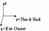
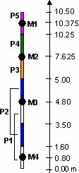
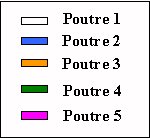
Figure 1.1-c: Modeling each of the buildings
Building characteristics:
The characteristics of the beams and masses that were used to model each of the buildings are given in the tables below:
Mass |
Altitude |
Mass |
Mass inertia (\({10}^{3}{\mathit{kg.m}}^{2}\)) |
||
(\(m\)) |
(\({10}^{3}\mathit{kg}\)) |
\({J}_{\mathit{xx}}\) |
\({J}_{\mathit{yy}}\) |
\({J}_{\mathit{zz}}\) |
|
M1 |
10.38 |
79.25 |
410.72 |
482.34 |
893.06 |
M2 |
6.25 |
104.09 |
574.75 |
694.04 |
1268.79 |
M3 |
4.8 |
156.71 |
1020.85 |
1071.22 |
2092.07 |
M4 |
0.8 |
316.97 |
1846.7 |
1844.02 |
3690.72 |
Table 1.1-b: characteristics of the weights of the skewer model provided by NUPEC [bib1]
Beam |
Area (\({m}^{2}\)) |
Moment of inertia (\({m}^{4}\)) |
Shear coefficient |
Torsion constant (\({m}^{4}\)) |
||
\(A\) |
\({I}_{z}\) |
\({I}_{y}\) |
\({A}_{y}\) |
\({A}_{z}\) |
\({J}_{x}\) |
|
P1 |
59.50 |
341.33 |
341.33 |
1/0.93 |
1/0.93 |
682.70 |
P2 |
8.28 |
39.51 |
54.77 |
2.94 |
1.47 |
94.30 |
P3 |
63.19 |
341.33 |
341.33 |
1/0.99 |
1/0.99 |
682.70 |
P4 |
19.78 |
148.34 |
149.14 |
2.13 |
2.11 |
297.50 |
P5 |
64.00 |
341.33 |
341.33 |
1.00 |
1.00 |
682.70 |
Table 1.1-c: characteristics of the beams of the brochette model provided by NUPEC [bib1]
The geometry taken into account in Code_Aster is that of the structure of buildings as well as their foundation. Geometric and physical ground data are directly given to MISS3D.
1.2. Material properties#
The floor
The mechanical characteristics of the layers of the soil model that were used are those indicated in table 1.
The foundation and the building
E |
\(31000\mathit{MPa}\) |
NUDE |
0.16 |
RHO |
|
ALPHA |
0 |
1.3. Boundary conditions and mechanical loads#
Each of the 2 links between a 1D model and its foundation is achieved by a solid link condition between the foundation and the node common to the building model. This knot is blocked and a solid body movement is imposed on the floor.
We excite the top of the building model in the direction \(Y\), which is the direction of separation between the buildings, with a harmonic loading \(F\mathrm{=}{F}_{o}\mathrm{sin}\alpha t\) whose force module \({F}_{o}\) is \(10\mathit{kN}\) with a pulsation that varies from \(0\) to \(20\mathit{Hz}\) in steps of \(0.1\mathit{Hz}\).
For the buried configuration, the excitation is applied in the following way:
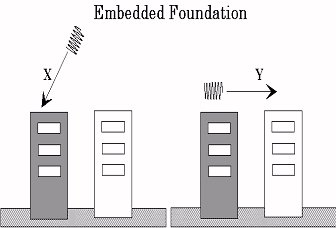
Figure 1.3-a: harmonic excitation configuration in a buried foundation