4. B modeling#
4.1. Characteristics of modeling#
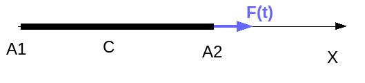
Modeling: BARRE
In this modeling, the square plate is modelled by a bar with a rectangular cross section of one meter wide and a thickness of 0.1 m.
4.2. Boundary conditions and loads#
Boundary conditions:
L location |
Blocked components |
A1 |
DX, DY, DZ |
C |
DX, DZ |
Loads:
The force is affected in A2, it is a nodal force that must be multiplied by the width of the plate to be equivalent to modeling A.
4.3. Characteristics of the mesh#
Knots: 4
Meshes: 3 SEG2
4.4. Tested sizes and results#
Three calculations are performed, the first with DYNA_NON_LINE in an explicit diagram and MASS_DIAG =” NON “(this calculation is cut in two in order to test the correct transmission of the observation table), the second with DYNA_NON_LINE in an explicit diagram and MASS_DIAG =” OUI” and the third with DYNA_VIBRA without a diagonal mass matrix.
First calculation:
Identification |
Reference |
Reference type |
Tolerance |
Displacement \(\mathit{DX}\) in \(A2\), INST = 1,2E-3 |
3.51957D-05 |
“ANALYTIQUE” |
0.05% |
Displacement \(\mathit{DX}\) in \(A1\), INST = 3E-4 (via observation table) |
“ANALYTIQUE” |
0.1% |
|
Displacement \(\mathit{DX}\) in \(A1\), INST = 9E-4 (via observation table) |
“ANALYTIQUE” |
0.1% |
Second calculation:
Identification |
Reference |
Reference type |
Tolerance |
Displacement \(\mathit{DX}\) in \(A2\), INST = 1,2E-3 |
3.51957D-05 |
“ANALYTIQUE” |
0, 5% |
Third calculation:
Identification |
Reference |
Reference type |
Tolerance |
|
ECIN_ELEM, \(M21\) mesh, Comp. TOTALE |
9.10387D-02 |
“ANALYTIQUE” |
0.5% |
0.5% |