1. Reference problem#
1.1. Geometry#
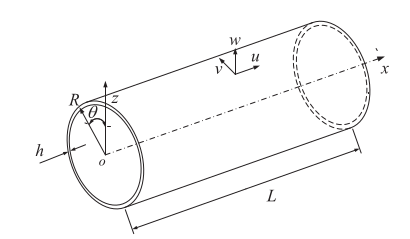
Fig. 1. Diagram of pipe geometry
Average radius: \(R=0.050m\)
Pipe thickness: \(h=0.0025m\)
Length: \(L=1m\)
The vectors \(\vec{x}\), \(\vec{\mathrm{\theta }}\), and \(\vec{z}\) represent the axial, circumferential, and radial directions of the pipe.
Displacements in the \(\vec{x}\), \(\vec{\mathrm{\theta }}\), and \(\vec{z}\) directions are noted by \(u\), \(v\), and \(w\).
1.2. Material properties#
The properties of the material from which the pipe is made are:
\(E=2.{10}^{11}\mathrm{Pa}\) |
Young’s module |
\(\mathrm{\mu }=0.3\) |
Poisson’s ratio |
\(\mathrm{\rho }=7800\mathit{kg}/{m}^{3}\) |
Volume density |
1.3. Boundary conditions and loads#
Eigenmodes are calculated under five different boundary conditions:
FF: both ends of the pipe are free;
SF: one end is free and the other is in simple support;
SS: both ends are in simple support;
CS: one end with simple support and the other embedded;
CC: both ends are recessed.
where F, S, and C represent simply-supported, clamped, and*free* in English.
No load.
1.4. Initial conditions#
Not applicable