3. Reference problem: Multi-fiber beams#
3.1. Geometry and meshes#
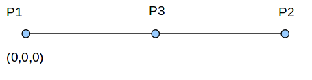
We consider a beam with a length \(2m\) and a square cross section with a side \(0.2m\).
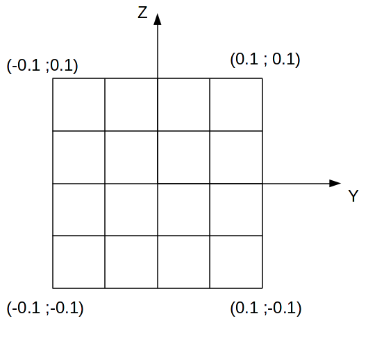
For multifibre beam models, the section of the beam includes 16 fibers arranged as in the following figure:
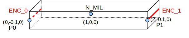
This same beam is also represented by 3D geometry.
3.2. Material properties#
The materials are linear elastic:
Concrete: \(E\mathrm{=}30\mathit{GPa}\) steel: \(E\mathrm{=}200\mathit{GPa}\)
\(\nu \mathrm{=}0.2\) \(\nu \mathrm{=}0.3\)
\(\alpha \mathrm{=}{10}^{\mathrm{-}5}{K}^{\mathrm{-}1}\) \(\alpha \mathrm{=}2.{10}^{\mathrm{-}5}{K}^{\mathrm{-}1}\)
In the first calculation (mono-material), the beam is entirely made of concrete.
In the second and third calculations (bi-material), the fibers under the \(Y\) axis are concrete while the fibers above are steel.
3.3. Boundary conditions and loading#
3.3.1. Boundary conditions#
Beams calculations 1 and 2:
Node P1 is stuck in DX, DY, DZ, DRX, and DRZ.
Node P2 is locked in DY and DZ.
Beams calculation 3:
The nodes P 1 and P 2 are embedded.
3D:
The nodes on segment ENC_0 are locked in DX and DZ.
The nodes on segment ENC_1 are locked in DZ.
The nodes P0 and P1 are locked in DY.
3.3.2. Loading#
Mono-material calculation:
A thermal loading dependent on \(Z\) and on the time \(t\) is imposed. Temperature is defined as: \(T\mathrm{=}(\mathrm{-}200Z+20)t\). The reference temperature is \(0\).
Bi-material calculations:
A thermal loading dependent on \(Z\) and on the time \(t\) is imposed. Temperature is defined as follows:
\(T\mathrm{=}20t\) if \(Z>0\)
\(T\mathrm{=}40t\) if \(Z<0\)
The reference temperature is \(0\).