5. C modeling#
5.1. Characteristics of modeling#
In this modeling, we validate the use of the macro-command MACR_ECREVISSE in relation to rotation and translation. So it is not a non-regression test.
Indeed, Crayfish results depend only on the characteristics of the crack, including the direction. It is influenced by gravity. Thus, cracks with the same characteristics and having a symmetric direction with respect to the vertical must give the same flows.
We work with the same parameters (of the material, of the flow of the crack) as in modeling A (§ 1.1). The mesh is also the same except that it is rotated and translated. Details of the mesh are given in §5.2.
5.2. Meshing and boundary conditions.#
The two meshes used were obtained by rotation and translation of the modeling A mesh, so they maintain the same dimensions. They are featured in the and.
For the first mesh, the first curvilinear abscissa of the crack is the point of origin of the \((0;0)\) axes.
The second mesh results from a 120 degree rotation of the first mesh around the origin and a translation of vector \((\mathrm{-}10;20)\).
The boundary conditions for both meshes are analogous to modeling A:
The sides named FIXE1 (or FIXE2) are embedded (\(\mathit{DX}\mathrm{=}0\), \(\mathit{DY}\mathrm{=}0\)).
A contact condition is defined between lips BFISH1 - BFISB1 (BFISH2 - BFISB2) (DEFI_CONTACT).
The pressure and the temperature on the intrados INTRA1 (INTRA2) are greater than on the extrados EXTRA1 (EXTRA2): (\(1.E6\mathrm{Pa}\) and \(140°C\) versus \({P}_{\mathrm{atm}}\) and \(20°C\)). This causes the flow from the intrados to the extrados.
At the beginning of the calculation, the material is considered to be at ambient temperature \(20°C\), which is the reference temperature.
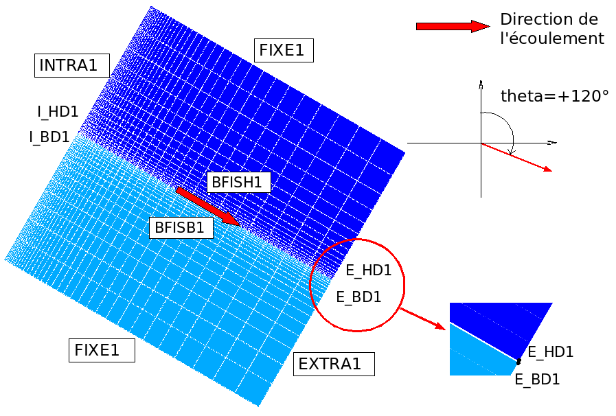
Figure 5.2-a : Mesh 1 for the direction \(\mathit{theta}\mathrm{=}120°\) (compared to the vertical) .
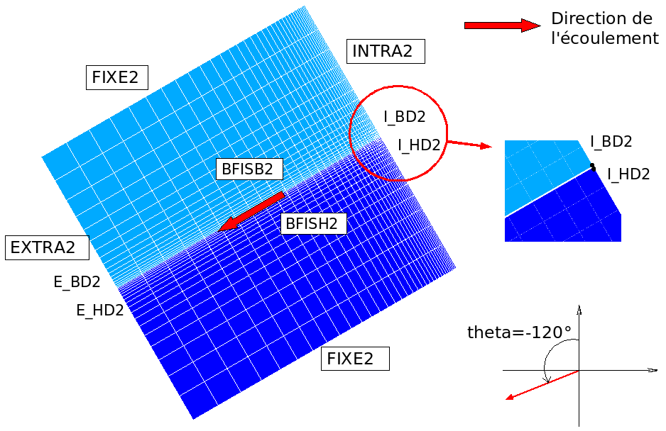
Figure 5.2-b : Mesh 2 for the direction \(\mathit{theta}\mathrm{=}\mathrm{-}120°\) (compared to the vertical) .
5.3. Tested sizes and results#
We’re testing the results at moment \(t=10000s\). The values of the result of mesh 2 are extracted, and they are compared to those corresponding to mesh 1.
Mesh 1 |
Mesh 2 |
Move \(\mathit{DX}\) to node \({E}_{\mathit{HD1}}\) |
by symmetry: (-1) * Move \(\mathit{DX}\) to node \({E}_{\mathit{BD2}}\) |
Move \(\mathit{DX}\) to node \({E}_{\mathit{BD1}}\) |
by symmetry: (-1) * Move \(\mathit{DX}\) to node \({E}_{\mathit{HD2}}\) |
Move \(\mathit{DY}\) to node \({E}_{\mathit{HD1}}\) |
by symmetry: Move \(\mathit{DY}\) to node \({E}_{\mathit{BD2}}\) |
Move \(\mathit{DY}\) to node \({E}_{\mathit{BD1}}\) |
by symmetry: Move \(\mathit{DY}\) to node \({E}_{\mathit{HD2}}\) |
Material temperature at node \({I}_{\mathit{HD1}}\) |
Material temperature at node \({I}_{\mathit{HD2}}\) |
Total flow |
Total flow |
Convection coefficient first abs. curv. |
Convection coefficient first abs. curv. |
First pressure abs. curv. |
First pressure abs. curv. |
Primary fluid temperature abs. curv. |
Primary fluid temperature abs. curv. |
Fluid heat flow first abs. curv. |
Fluid heat flow first abs. curv. |
Size |
Tolerance |
Move \(\mathit{DX}\) at nodes \({E}_{\mathit{HD1}}\) |
1.0E-05 |
Move \(\mathit{DX}\) to node \({E}_{\mathit{BD1}}\) |
1.0E-05 |
Move \(\mathit{DY}\) to node \({E}_{\mathit{HD1}}\) |
1.0E-05 |
Move \(\mathit{DY}\) to node \({E}_{\mathit{BD1}}\) |
1.0E-05 |
Material temperature at node \({I}_{\mathit{HD1}}\) |
1.0E-04 |
Total flow |
1.0E-03 |
Convection coefficient first abs. curv. |
1.0E-04 |
First pressure abs. curv. |
1.0E-04 |
Primary fluid temperature abs. curv. |
1.0E-04 |
Fluid heat flow first abs. curv. |
1.0E-03 |
5.4. notes#
The lips are in contact, the DEFI_CONTACT command is activated. The flow calculation is carried out with the residual opening.