4. C modeling#
4.1. Geometry#
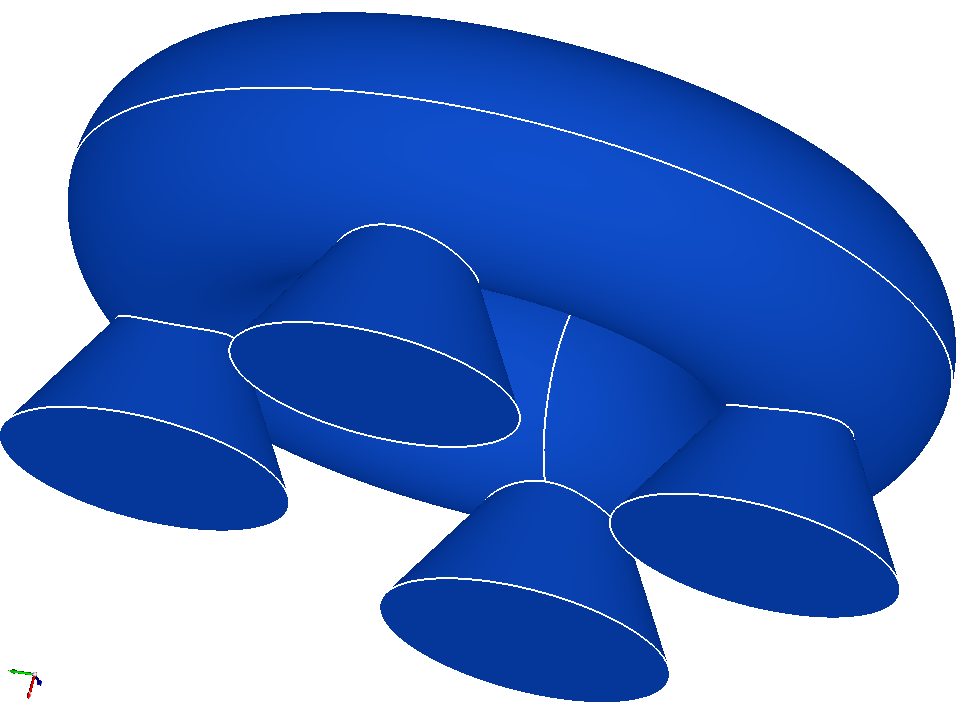
The structure is a torus centered on the origin and has an Ox axis. Its radius of revolution is 400 and the radius of the disk that rotates around the axis is 160. The feet are cones with an Ox axis and a 30-degree angle.
4.2. Material properties#
The material is an elastic material with a Young’s modulus E = 180,000 Pa and a Poisson’s ratio n = 0.3 S.I.
4.3. Boundary conditions and loads#
The calculation is in nonlinear mechanics. We will look at the evolution of the displacement on two nodes located on the base of two feet.
The piece is stuck on the base of the first foot:
Side C_1_base: DX = DY = DZ = 0
Pressure is applied to the base of the third foot:
C_3_base side: PRES = 1.0 103
The other edges have zero stress.
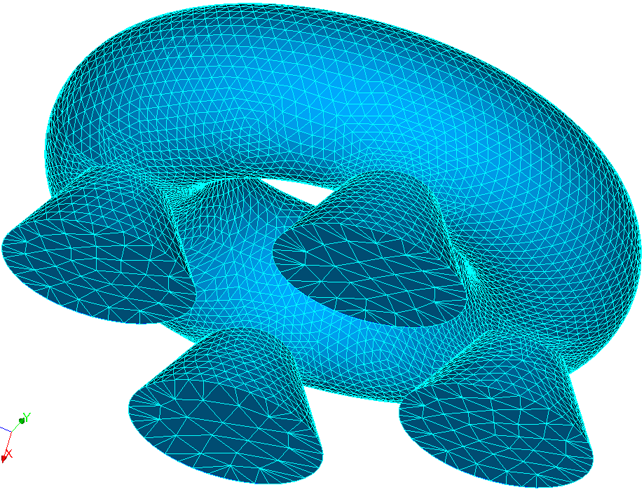
4.4. Characteristics of the initial mesh#

Knots: 3 323
SEG3: 133
TRIA6: 932
TET10: 1,723
The intersections between the cones and the torus are finely meshed by segments,
4.5. Adapted meshes#
The first adaptation is total uniform refinement. The number of tetrahedra is therefore multiplied by 8:13,784.
The second adaptation is a uniform refinement of the foot surfaces:
Knots: 29,500
SEG3: 448
TRIA6: 6,336
TET10: 17,078
The third adaptation is a uniform refinement of the torus face:
Knots: 51 130
SEG3: 532
TRIA6: 14,152
TET10: 26,976
4.6. Benchmark results#
DX displacement for the S_2 and S_4 node groups , consisting of a single node at the base of legs 2 and 4:
After adaptation 2 |
After adaptation 2 |
|
S_2 |
-627.975420185 |
-628.773696974 |
S_4 |
-152.344709784 |
-152.436880132 |
4.7. notes#
It can be seen that the nodes resulting from the division of the segments on the borders will be placed on the analytical description of the border.
We will carefully look at the mechanism used to archive and review adaptation histories.