4. Operands#
CALC_GP is a macro command and therefore calls other Code_Aster commands internally. Most of the keywords are passed on as they are to the other commands. We will then indicate in which command (s) the keywords are used.
4.1. Operand RESULTAT#
♦ RESULTAT = summary, [result]
Refers to the result of the thermo-mechanical calculation for which the parameter \({G}_{P}\) is calculated.
Used by POST_ELEM and CALC_CHAMP.
4.2. Operand LIST_INST#
♦ LIST_INST = instant, [L_r]
List of times at which the parameter will be calculated.
Attention: the quantities from which the parameter \({G}_{P}\) is calculated are non-linear, no temporal extrapolation is allowed; if an instant is specified, this one must be part of the list of archiving times for the thermomechanical calculation.
Used by POST_ELEM, CREA_CHAMP, and CALC_CHAMP.
4.3. Operand PRECISION#
◊ PRECISION = /prec, [R]
/1E-6 [DEFAUT]
Precision at which the list of moments should be considered.
4.4. Operand CRITERE#
◊ CRITERE = /” ABSOLU “[DEFAUT]
/” RELATIF “
Refers to the type of precision for determining the list of moments.
4.5. Operand GP_MAX#
◊ GPMAX = CO (“TABGPMAX”) [CO]
Indicates whether the user wants to obtain a second table as a result, a mandatory restriction of the complete table containing only the row where the maximum of the \({G}_{P}\) parameter is present for each calculation moment.
4.6. Operand TRANCHE_2D#
◊ TRANCHE_2D =_F (
♦ ZONE_MAIL = /” NON “
= /” OUI “
#Si ZONE_MAIL = “OUI”:
♦ GROUP_MA = l_group [l_group_ma]
♦ TAILLE = l_size [L_r]
#Si ZONE_MAIL = “NON”:
♦ TAILLE = size [R]
♦ CENTRE = center [R, R, R]
♦ RAYON = \(R\) [R]
♦ ANGLE = \(\theta\) [R]
♦ NB_ZONE = n [I]
◊ CHAMP_VISU = CO (“CHAMP”) [CO]
Refers to all the geometric parameters necessary to calculate the energy parameter.
4.6.1. Keyword ZONE_MAIL#
♦ ZONE_MAIL = /” NON “
= /” OUI “
Indicates whether the mesh represents the geometry of the chip areas.
If “OUI”, we are in the case of a mesh such as in Figure.
4.6.2. Case ZONE_MAIL = “OUI”#
4.6.2.1. Keyword GROUP_MA#
♦ GROUP_MA = l_group [l_group_ma]
List of cell groups on which calculations will be performed. Each group of elements must correspond to a chip area.
Used by POST_ELEM.
4.6.2.2. Keyword TAILLE#
♦ TAILLE = l_size [L_r]
List of zone sizes. This list should be the same size as the mesh group list.
4.6.3. Case ZONE_MAIL = “NON”#
In this case, a geometric calculation area is constructed by the macro. The following parameters are used to define it. Figure shows the parameters for defining these zones; it represents a notch with center \({C}_{\mathit{ent}}\), radius \(R\); the third zone \({C}_{3}(l)\) of length \(3\mathrm{\times }{l}_{C}\) is shaded.
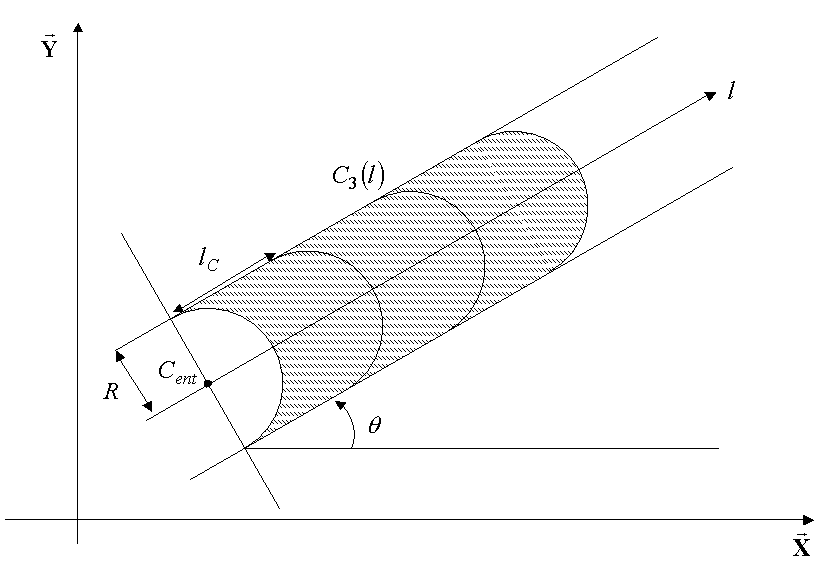
Figure 4-1- Geometric definition of areas in the non-meshed case.
4.6.3.1. Keyword TAILLE#
♦ TAILLE = \({l}_{C}\) [R]
Increment in the size of the zones. The zone is therefore of size n* \({l}_{C}\).
Used by FORMULE.
4.6.3.2. Keyword CENTRE#
♦ CENTRE = center [R, R, R]
Indicate the coordinates of the center of notch \({C}_{\mathrm{ent}}\) in the global coordinate system.
Used by FORMULE.
4.6.3.3. Keyword RAYON#
♦ RAYON = \(R\) [R]
Refers to the radius of the notch.
Used by FORMULE.
4.6.3.4. Keyword ANGLE#
♦ ANGLE = \(\theta\) [R]
Refers to the angle formed between the direction of the notch and the \(\overrightarrow{X}\) axis of the global coordinate system.
The angle should be given in degrees and measured trigonometrically.
Used by FORMULE
4.6.3.5. Keyword NB_ZONE#
♦ NB_ZONE = n [I]
Refers to the number of zones (chips) considered in the calculation.
4.6.3.6. Keyword CHAMP_VISU#
◊ CHAMP_VISU = CO (“CHAMP”) [CO]
If the user wishes, he can request the output of a field at the Gauss points representing the chips. The value for this field is \(1\) in the chip zone and \(0\) elsewhere. Figure shows a visualization of this field for the mesh shown in Figure.
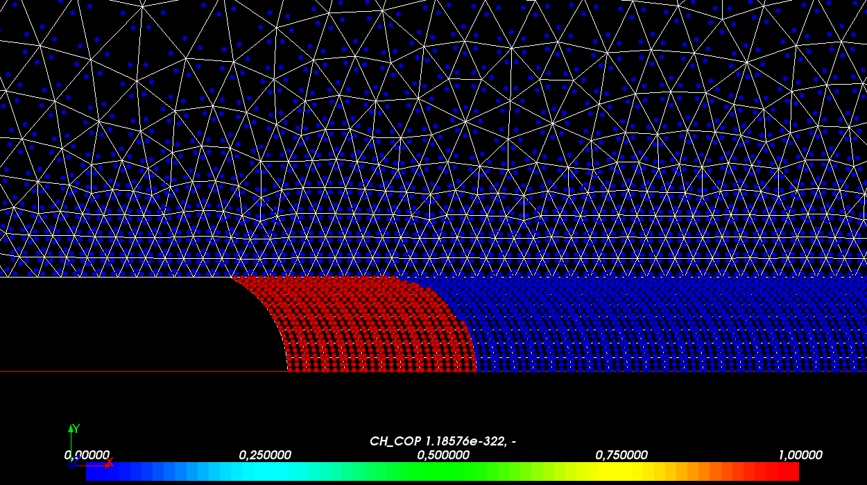
Figure 4-2- Field of visualization of the chips.
4.7. Operand TRANCHE_3D#
◊ TRANCHE_3D =_F (
♦ GROUP_MA = l_group [l_group_ma]
)
4.7.1. Keyword GROUP_MA#
♦ GROUP_MA = l_group [l_group_ma]
List of cell groups on which calculations will be performed.
Each group of elements should correspond to a chip zone.
Each list of groups of elements corresponds to a given slice; the groups of cells within each list must correspond to the chips and be ordered from closest to the default background to the most distant.
Used by POST_ELEM.
4.8. Operand SYME#
#Dans the 2D case
♦ SYME = /” OUI “
/” NON “
Indicate whether a symmetry of the structure with respect to the notch allowed only half of the structure to be meshed. In figures and, only the part of the structure greater than the notch is defined; in this case, the user will enter SYME =” OUI “and the result indicated in the table will take account of symmetry (multiplied by two).
4.9. Operand FOND_FISS#
#Si TRANCHE_3D:
♦ FOND_FISS = background [background]
In 3D, the user must first define a crack bottom, with a detached lip (since the defect is represented by a cut).
This crack background allows in particular the calculation of surfaces (denominator of the calculation of \({G}_{p}\)).