3. Gp energetic elasto-plastic rupture model#
The energy model for predicting breakage in elasto-plasticity is described in more detail in the reference documentation [R7.02.16].
The aim of this model is to estimate the critical cleavage initiation load in an elasto-plastic structure; it therefore represents a deterministic alternative to models based on the main stress levels that are Beremin or Bordet (also available in Code_Aster).
The model is based on a representation of the defect by a notch; the principle of minimizing the potential energy of the structure in relation to the advance of the defect only makes it possible to arrive at a criterion on the average elastic energy present in particular zones \(C(l)\) downstream of the notch and commonly called chips. The Figure shows a definition of these zones, which are therefore measured from the bottom of the notch to a distance \(l\); \({L}_{C}\) represents the diameter of the notch here.
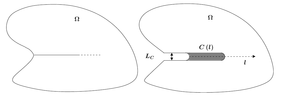
Figure 3-1- Definition of the area of interest.
The cleavage criterion is then written:
\((\mathrm{\exists }l>0)\tilde{{G}_{P}}(l)\ge {G}_{\mathit{PC}}\) with \(\stackrel{̃}{{G}_{P}}\left(l\right)=\frac{{\int }_{C\left(l\right)}{\Phi }_{\mathit{el}}^{\mathit{traction}}d\Omega }{l}\),
where \({\Phi }_{\mathit{el}}^{\mathit{traction}}=\frac{\lambda }{2}H(\mathit{tr}(ϵ))\mathit{tr}{(ϵ)}^{2}+\mu \sum _{i=1}^{3}H({ϵ}_{i}){ϵ}_{i}^{2}\), \(H\) represents the Heaviside function, \(ϵ\) represents the elastic deformation tensor, \({ϵ}_{i}\) represents the main elastic deformations, and \({G}_{\mathrm{PC}}\) is a material parameter to be determined. In 3D, the distance \(l\) is replaced by the area of the chip in the plane of propagation of the notch.
In order to calculate the elastic energy in these areas called chips, two solutions exist in 2D:
have defined these areas in mesh \({\Phi }_{\mathit{el}}^{\mathit{traction}}=\frac{\lambda }{2}H(\mathit{tr}(ϵ))\mathit{tr}{(ϵ)}^{2}+\mu \sum _{i=1}^{3}H({ϵ}_{i}){ϵ}_{i}^{2}\)
define these areas a posteriori in the free mesh \({\Phi }_{\mathit{el}}=\frac{1}{2}\sigma {A}^{-1}\sigma\)
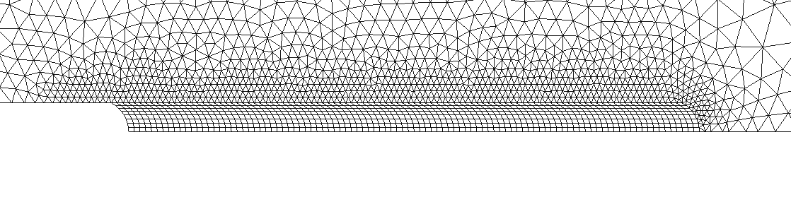
Figure 3-2- Classic mesh with chip definition.
In the first case, Figure shows a view of the mesh to be used. This mesh comprises 95 small-sized chips (each meshed by 8 quadrangular finite elements), then a deraffination zone. A group of elements must then be associated with each chip.
In the second case, Figure shows the possibility of meshing around the notch. This mesh must be sufficiently fine in this zone in order to allow reliable calculation of the parameter of the energy method.

Figure 3-3- Free mesh without chip definition.
In 3D, the concept of slice is introduced, each slice containing several chips. The slices follow one another along the defect front, which is a line. In 2D, there is only one slice, the default background being reduced to 1 point. We define the chips of the 1st slice in the same way as in 2D, with the difference that the meshes are volume and are necessarily hexahedral; we continue the list by adding the chips from the 2nd slice in the same way; we finally obtain a list of \({\mathrm{nb}}_{\mathrm{copeaux}}\times {\mathrm{nb}}_{\mathrm{tranches}}\) groups of cells.
Tranche No. 1
Tranche No. 2
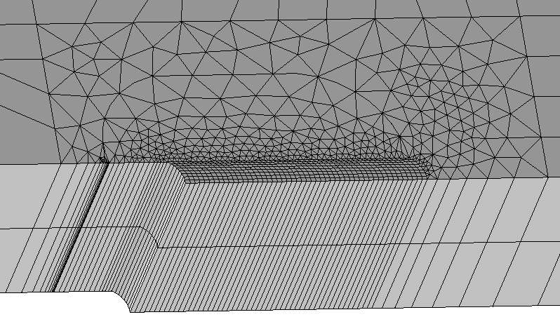
Figure 3-4 Definition of slices