5. Implementation: hole or underthickness#
In order to represent a hole or an underthickness by X- FEM, we use the definition of an interface, which represents the border of the hole or underthickness. Take the example of a plate that has a lack of material on one of its sides (gray region of Figure 5-a). This lack of matter can be modelled according to its shape by a portion of an ellipse. Reference may be made to the analytical test case of the perforated plate (FORMA01, modeling C), or to the validation case representative of an industrial study SSLA105 (restricted access).
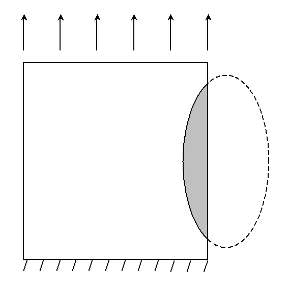
Figure 5-a : example of an underthickness on the edge of a plate
The interface between the plate and the void is then represented by an elliptical inclusion level-set, whose formula is simply written:
LN= FORMULE (NOM_PARA =( “X”, “Y”), VALE =” (X-Cx) **2/ (b*b) + (Y-Cy) **2/ (a*a) -1. “)
where \((\mathit{Cx},\mathit{Cy})\) are the coordinates of the center of the ellipse and \(a\) and \(b\) are the lengths of the ellipse’s semi-axes.
As in the case of an interface between 2 solids in contact, only the normal level-set should be defined, the tangential level-set being useless here. In DEFI_FISS_XFEM, we will only enter FONC_LN and we will specify the type of discontinuity: TYPE_DISCONTINUITE =” INTERFACE “.
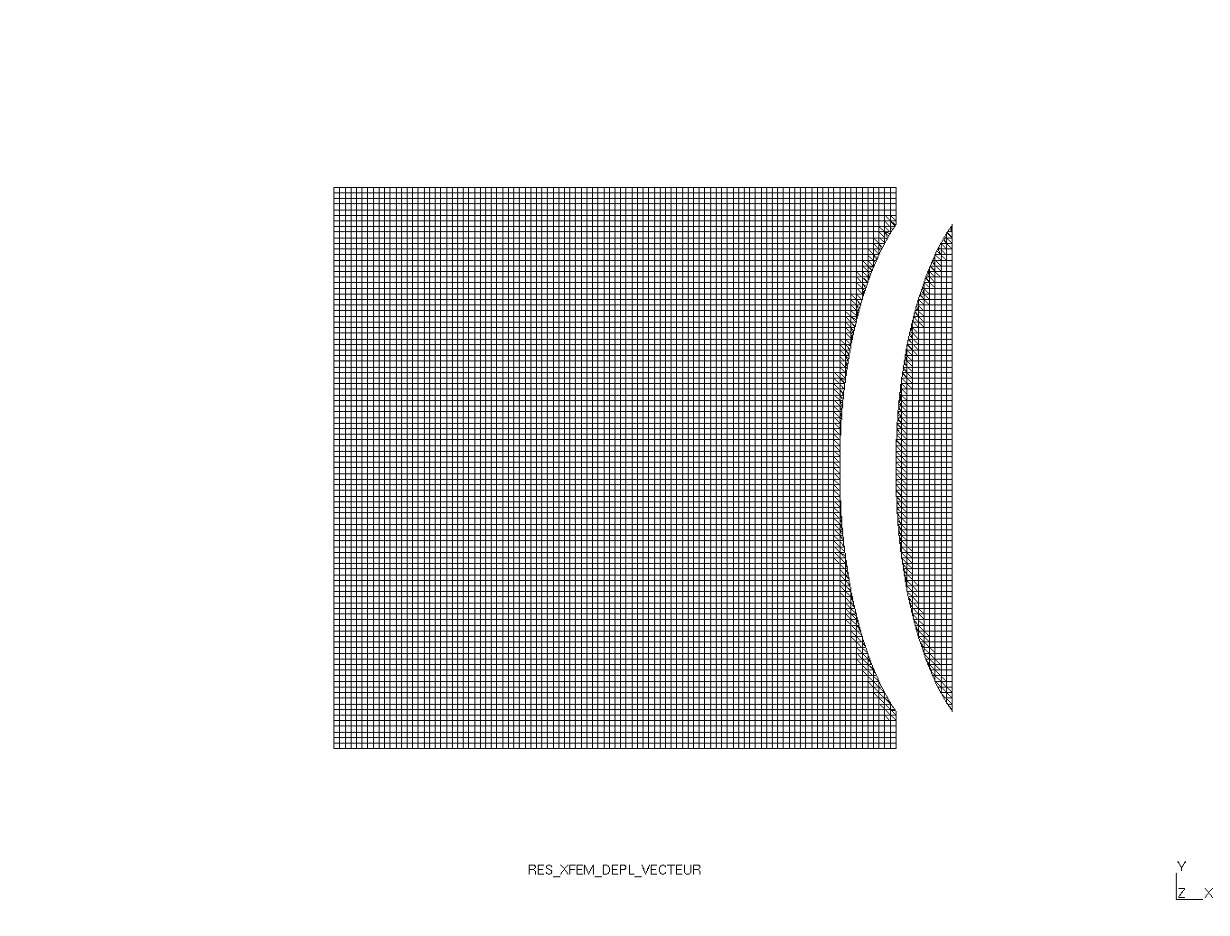
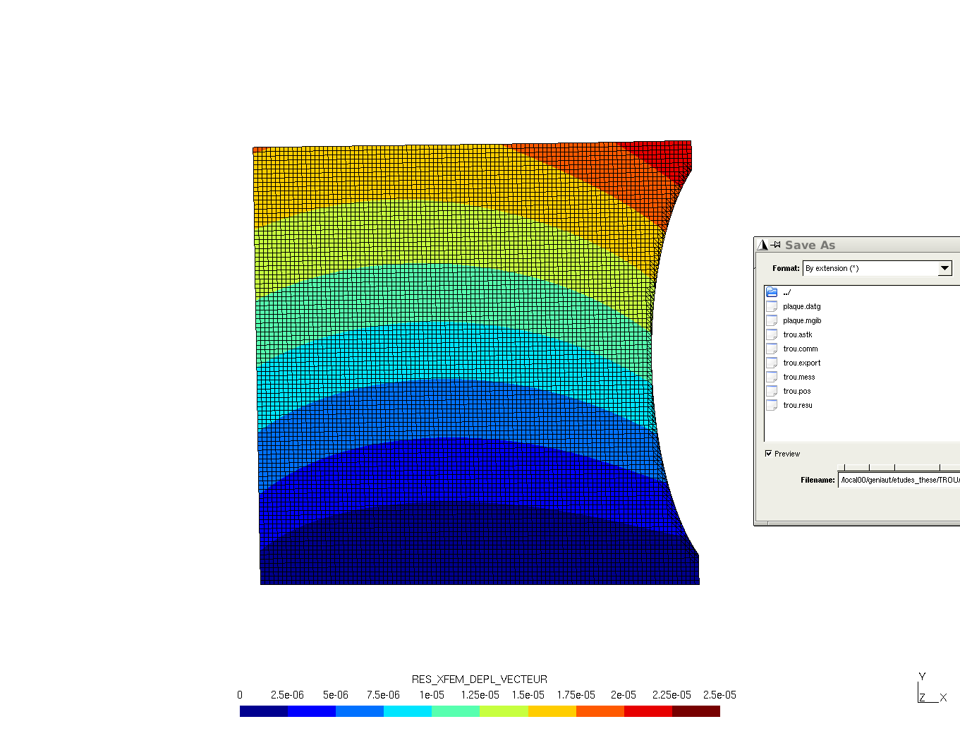
Figure 5-b : deformed unamplified (left) and amplified (right)
The procedure is the same as for a non-contact case. But care must be taken to block rigid modes in the empty part, for example by blocking two nodes in the gray part. It is even better to impose a significant displacement on these two nodes, so that it transfers the empty part away from the plate. This device allows you to visualize only the plate without the empty part (see Figure 5-b). Reminder: use MECA_STATIQUE or STAT_NON_LINE for resolution. In the case of the test case of the plate with holes (FORMA01C), the boundary conditions that make it possible to represent only a quarter of the plate also block the rigid modes of the empty part, so there are no specific boundary conditions to add in this case.
To impose a loading of pressure on the interface, you must proceed as for cracks: impose pressure on both sides of the interface (although imposing pressure only on the « in the material » side is sufficient). See § 2.6.