6. Examples#
The test cases selected illustrate the different possible uses of discrete elements.
6.1. Mass elements#
Modeling a point mass M_T_D_N
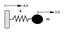
Fig. 6.1 Release with a simple spring weight.#
- Test case:
SDLD34 [V2.01.034]
Modelling:
SDLD34A DIS_T/M_T_D_N
SDLD34B DIS_T/M_T_D_N
Modeling a rotating M_TR_D_N point
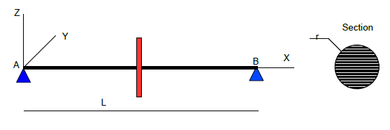
Fig. 6.2 Frequency of a simplified shaft line with gyroscopy.#
- Test case:
SDLL123 [V2.02.123]
Modelling:
SDLL123A DIS_TR/M_TR_D_N
SDLL123B DIS_TR/M_TR_D_N
SDLL123C DIS_TR/M_TR_D_N
SDLL123D DIS_TR/M_TR_D_N
SDLL123E DIS_TR/M_TR_D_N
SDLL123F DIS_TR/M_TR_D_N
Eccentric mass modelling
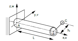
Fig. 6.3 Slender, free-embedded beam with eccentric mass or inertia.#
- Test case:
SDLL15 [V2.02.015]
Modelling:
SDLL15A DIS_TR/M_TR_D_N
6.2. Stiffness elements#
Support stiffness modelling
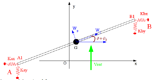
Fig. 6.4 Beam subject to a wind speed field.#
- Test case:
SDNL102 [V5.02.102]
Modelling:
SDNL102A DIS_T/K_T_D_L
Modeling of non-symmetric stiffness and damping matries
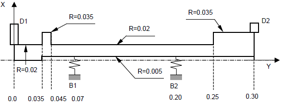
Fig. 6.5 Harmonic response of a rotor with two disks and two non-symmetric bearings, subject to the gyroscopic effect.#
- Test case:
SHLL103A [V2.06.103]
Modelling:
SHLL103A DIS_TR/K_TR_N/A_TR_N
Modeling simple structural elements
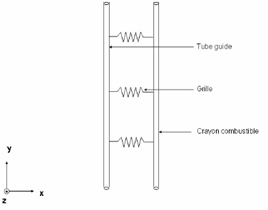
Fig. 6.6 Identification of fluid forces on a wire structure.#
- Test case:
SDLS139A [V2.03.139]
Modelling:
SDLS139A DIS_TR/K_TR_D_N
Modeling of distributed ground stiffness
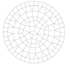
Fig. 6.7 Response of a rigid circular foundation to a seismic excitation that varies in space.#
- Test case:
SDLS118 [V2.03.118]
Modelling:
SDLS118C DIS_TR/K_TR_D_N
SDLS118D DIS_TR/K_TR_D_N
Modeling of distributed ground stiffness with detachment
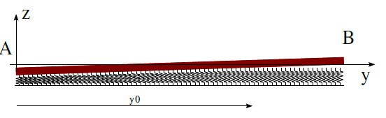
Fig. 6.8 Non-deformable plate on a spring mat.#
- Test case:
SSNL130 [V6.02.130]
Modelling:
SSNL130A DIS_T/K_T_D_L
SSNL130B 2D_DIS_T/K_T_D_L
- Note:
Use of the DIS_CHOC law
Modeling a bolted assembly
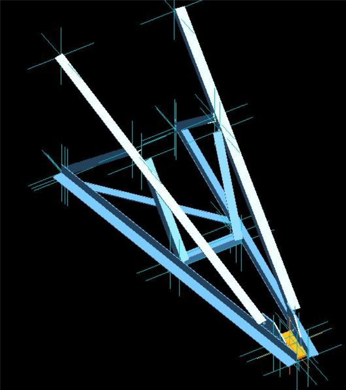
Fig. 6.9 Determination of the ruin loads of the console MEKELEC.#
- Test case:
SSNL135 [V3.03.020]
Modelling:
SSNL135A DIS_TR
SSNL135B DIS_TR
SSNL135C DIS_TR
- Note:
Each bolt is represented by a discrete element of zero length and its stiffness K_TR_D_L.
Modeling a rotor crack
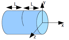
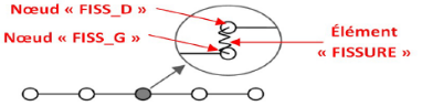
Fig. 6.10 Rotating cracked rotor, subjected to a bending force.#
- Test case:
SDNL133 [V5.02.133]
Modelling:
SDNL133A DIS_TR
- Note:
See the documentation Instructions for implementing rotor calculations [U2.06.32].
6.3. Damping elements#
The documentation for modeling mechanical damping is:
[R5.05.04] Modeling damping in linear dynamics
[U2.06.03] Mechanical damping modeling instructions
Viscous damping modelling
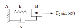
Fig. 6.11 Transient dynamic response of a harmonic oscillator with variable damping#
- Test case:
SDLD321 [V2.01.321]
Modelling:
SDLD321A DIS_T/K_T_D_L M_T_L A_T_D_L
SDLD321B DIS_T/K_T_D_L M_T_L A_T_D_L
SDLD321C DIS_T/K_T_D_L M_T_L A_T_D_L
Hysteretic damping modelling
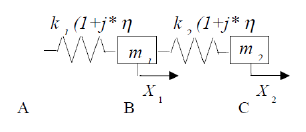
Fig. 6.12 2 degrees of freedom spring mass system with hysteretic damping#
- Test case:
SDLD313 [V2.01.313]
Modelling:
SDLD313A DIS_T/K_T_D_L M_T_L
6.4. Other uses#
6.4.1. Charging application or point boundary conditions.#
Cracked cylinder under multiple loads
Fig. 6.13 Cracked cylinder under multiple loads#
- Test case:
SSNV166 [V6.04.166]
Modelling: zero stiffness and mass
SSNV166A DIS_TR/K_TR_D_N M_TR_D_N
SSNV166B DIS_TR/K_TR_D_N M_TR_D_N
SSNV166C DIS_TR/K_TR_D_N M_TR_D_N
In this 3D model, a loading of torsional and flexure is applied to the upper face of the cylinder via a POI1 mesh and a LIAISON_ELEM connection.
Dynamic response of a free-standing recessed pipe girder.
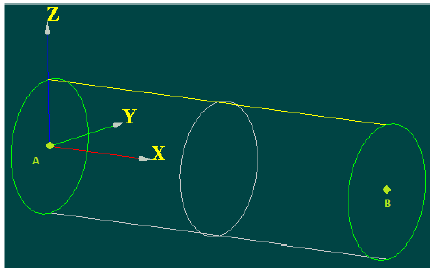
Fig. 6.14 Dynamic response of a free-standing recessed pipe girder.#
- Test case:
SDLL135 [V2.02.135]
Modelling: zero stiffness and mass
SDLL135F DIS_TR/K_TR_D_N M_TR_D_N
In this model DKT, the nodes located in section A are linked (LIAISON_ELEM) to a discrete element DIS_TR (dot type mesh POI1 located in A) with 6 degrees of freedom, which is totally fixed to it.
Modeling a model made up of nodes for the projection of results
Fig. 6.15 Simulation of a strain gauge using the OBSERVATION command.#
- Test case:
SDLV131 [V2.04.131]
Modelling: zero stiffness and mass
SDLV131A DIS_T
SDLV131B DIS_T
SDLV131C DIS_T
SDLV131D DIS_T
6.4.2. Creation of a numerical model for the comparison of experimental results.#
SDLS112B: Extrapolation of measurements on a 2D model (GARTEUR test)
SDLV122A: Extrapolation of local measurements onto a complete (3D) model [V2.04.122].
SDLD104A /B: Extrapolation of local measurements on a complete (discrete) model.
Taking into account the contact (via operator DEFI_CONTACT) between two POI1 meshes of zero stiffness.
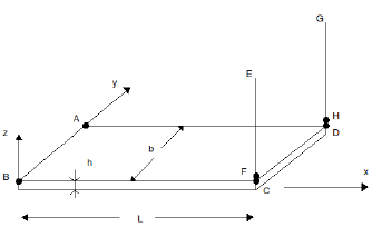
Fig. 6.16 Embedded plate subjected to bending by beams in contact with the free edge.#
- Test case:
SSNL107 [V2.04.131]
Modelling:
SSNL107A DIS_TR
SSNL107B DIS_TR
SSNL107C DIS_TR