4. Thermomechanical chaining#
4.1. Formalism#
For the resolution of chained thermomechanical problems, one must use thermal shell finite elements [R3.11.01] for the thermal calculation of which the temperature field is retrieved as the input data of the Code _Aster for mechanical calculation. There must therefore be compatibility between the thermal field given by the thermal shells and that recovered by the mechanical shells. The latter is defined by the knowledge of the 3 fields TEMP_INF, TEMP_MIL and TEMP_SUP given in lower, middle and upper shell skins. The table below shows these compatibilities:
Modeling THERMIQUE |
Mesh |
Element |
Mesh |
Element |
Modeling |
Modeling MECANIQUE |
COQUE |
|
|
|
|
|
|
COQUE |
|
|
||||
COQUE |
|
|
|
MEDSQU4 MEQ4QU4 |
DST Q4G |
|
COQUE |
|
|
|
|
|
|
COQUE |
|
|
||||
COQUE |
|
|
|
MEDSTR3 |
DST |
|
COQUE_PLAN |
|
|
||||
COQUE_AXIS |
|
|
|
|
|
Notes:
The nodes of thermal shell elements and mechanical plates or shells must match. The meshes for thermal and mechanical engineering will therefore have the same number and the same type of meshes.
Surface thermal shell elements are treated as plane elements by projecting the initial geometry onto the plane defined by the first 3 vertices. For the chaining of calculations with mechanical curved elements, it is therefore necessary that the geometry of the plate is not too far from that of the shell. When the structure is curved, for the thermal calculation, it therefore requires meshing it finely enough so as to have correct results in preparation for the mechanical part. Only the linear thermal elements are perfectly associated with the corresponding linear elements in mechanics because taking into account the curvature of the mesh structure.
Chaining with multi-layered materials is not available at this time.
Thermomechanical chaining is also possible if one knows, analytically or through experimental measurements, the variation of the temperature field in the thickness of the structure or of certain parts of the structure. In this case we work with a temperature map defined a priory; the temperature field is no longer given by the three values TEMP_INF, * TEMP_MILet TEMP_SUPdu thermal calculation obtained by EVOL_THER. The operator DEFI_NAPPE makes it possible to create such temperature profiles from data provided by the user. These profiles are affected by the command CREA_CHAMP and and CREA_RESU (see the test case*hsns100b). Note that it is not necessary for mechanical calculation that the number of integration points in**the thickness be equal to the number of points of discretization of the temperature field in the thickness. The temperature field is automatically interpolated at the points of integration into the thickness of the plate or shell elements.
The thermal evolution that can be associated with the material field by AFFE_MATERIAU/AFFE_VARC must be ready to be used by the finite elements of the mechanical model. A problem arises for shell or pipe elements that use a temperature that varies in thickness on the various layers. For these elements, it is necessary to prepare the temperature calculation on the layers prior to the order AFFE_MATERIAU . To do this, the user must use the command CREA_RESU with the operation PREP_VARC (PREparation of the Command Variables ») which makes it possible to calculate the temperature in the layers of a shell starting either from a temperature defined by a function map or from a temperature calculated by*Code_Aster*with a shell model (TEMP_MIL/TEMP_INF/TEMP_SUP) *.
HPLA100
|
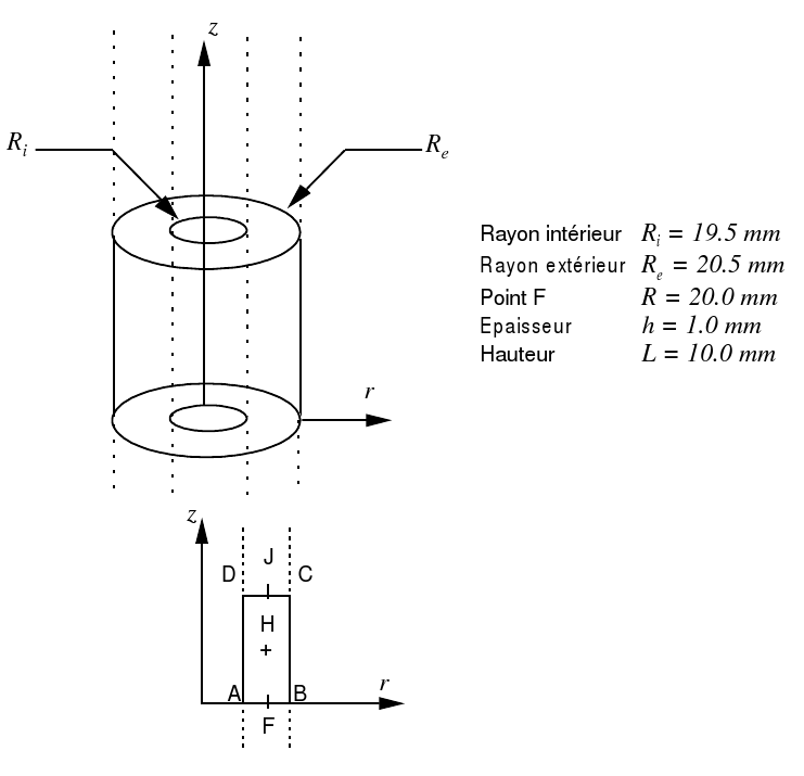
Title: Thermoelastic hollow cylinder weighing in uniform rotation
|