1. Reference problem#
1.1. Geometry#
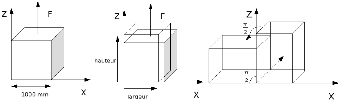
Figure1: Reference problem (for a \(90°\) rotation)
We consider a cubic element of matter with a side of \(1000\mathrm{mm}\) subjected alternately to a tensile force and then to an overall rotation of \(45°\). It undergoes a total of 4 traction/rotation cycles.
1.2. Material data#
Here we consider 6 elasto-plastic behavior laws with kinematic or combined kinematic/isotropic work-hardening of the von Mises type:
VMIS_CINE_LINE, VMIS_ECMI_LINE, VMIS_ECMI_TRAC,
VMIS_CIN1_CHAB and VMIS_CIN2_CHAB VMIS_CIN2_MEMO.
The table below lists the parameters used; in order to reinforce the comparison, the parameters used result in laws of behavior that are identical in all 5 cases (linear work hardening).
Keyword |
Setting |
Value |
ELAS |
E |
\(200000\mathrm{MPa}\) |
NUDE |
\(\mathrm{0,3}\) |
|
TRACTION |
SIGM |
\((0.001\mathrm{,200});(0.002\mathrm{,202})\) |
ECRO_LINE |
D_ SIGM_EPSI |
\(2000\mathrm{MPa}\) |
SY |
\(200\mathrm{MPa}\) |
|
PRAGER |
C |
\(\frac{2}{3}\frac{E\mathrm{\ast }\text{D\_SIGM\_EPSI}}{E\mathrm{-}\text{D\_SIGM\_EPSI}}\mathrm{\simeq }\mathrm{1346,8}\mathit{MPa}\) |
CIN1_CHAB |
C_I |
\(\frac{E\mathrm{\ast }\text{D\_SIGM\_EPSI}}{E\mathrm{-}\text{D\_SIGM\_EPSI}}\mathrm{\simeq }\mathrm{2020,2}\mathit{MPa}\) |
R_0 |
\(200\mathit{MPa}\) |
|
R_I |
\(200\mathit{MPa}\) |
|
G_0 |
\(0\) |
|
CIN2_CHAB |
C1_I |
\(\frac{1}{2}\frac{E\ast \text{D\_SIGM\_EPSI}}{E-\text{D\_SIGM\_EPSI}}\simeq \mathrm{1010,1}\mathrm{MPa}\) |
C2_I |
\(\frac{1}{2}\frac{E\ast \text{D\_SIGM\_EPSI}}{E-\text{D\_SIGM\_EPSI}}\simeq \mathrm{1010,1}\mathrm{MPa}\) |
|
R_0 |
\(200\mathrm{MPa}\) |
|
R_I |
\(200\mathrm{MPa}\) |
|
G1_0 |
\(0\) |
|
G2_0 |
\(0\) |
MEMO_ECRO |
MU |
0 |
Q_M |
0 |
|
Q_0 |
0 |
|
ETA |
\(0\) |
1.3. Boundary conditions and loads#
Two types of phases must be distinguished: traction phases and rotation phases. During the traction phases, the normal movements of the front and rear faces are blocked.
Traction phases:
First traction phase
Entity |
Load Type |
Value |
Underside |
FACE_IMPO |
|
Top side |
FACE_IMPO |
|
Rotation axis |
DDL_IMPO |
|
Front panel |
FACE_IMPO |
|
Back side |
FACE_IMPO |
|
Next pull-ups:
Entity |
Load Type |
Value |
Underside |
LIAISON_OBLIQUE |
|
Top side |
LIAISON_OBLIQUE |
|
Side \(X\mathrm{=}0\); \(Z\mathrm{=}\mathrm{1mm}\) |
|
|
Rotation axis |
DDL_IMPO |
|
Front panel |
DDL_IMPO |
|
Back side |
DDL_IMPO |
|
Each traction phase is composed of 5 identical increments.
Rotation phase:
Boundary conditions
Entity |
Load Type |
Value |
Rotation axis |
DDL_IMPO |
|
Front panel |
DDL_IMPO |
|
Back side |
DDL_IMPO |
|
The rotation load is imposed via a macro named CHAR_ROTA; an overall rotation of \(45°\) per phase is imposed, divided into 5 increments of \(9°\).
At the end of the loading, a deformation of 2,145 is obtained.