1. Reference problem#
1.1. Methodology#
Pre-tension consists in imposing a relative displacement between knots in the nut and knots in the stud. This relative displacement is imposed in the axis of the stud and must correspond to the desired tightening force. This relative displacement is imposed via the LIAISON_GROUP keyword of the AFFE_CHAR_MECA_F command.
For the user, it is therefore a question of determining the displacement to be imposed in order to find the desired tightening force. To do this, it is necessary to replay the study several times by modifying the value of the relative displacement until the required tightening force is reached.
This test case offers two models:
Modeling A: a model to illustrate manual adjustment.
B modeling: a model to illustrate automated realignment.
Note:
This method only applies to short trips.
It assumes that the difference in movements between the nut and the stud is constant over the entire area.
1.2. Geometry#
The geometry, shown in the figure, is generated by the « Flange calculation » business tool from SALOME - MECA -2012.1. The dimensions, in millimeters, are shown in the figure, these are the values proposed by default in the tool.
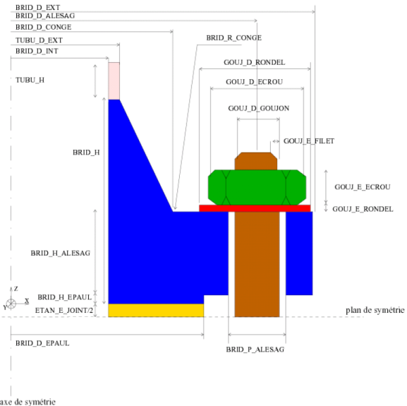
Figure 1.2-a: Geometry of the flange and the stud.
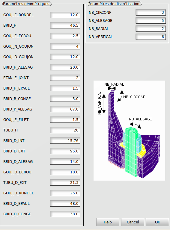
Figure 1.2-b: Geometry parameters.
1.3. Meshing#
The mesh, shown in the figure, is also generated by the « Flange calculation » business tool in SALOME - MECA -2012.1. It is linear and composed of 1108 hexahedra and 70 prisms for 1821 knots.
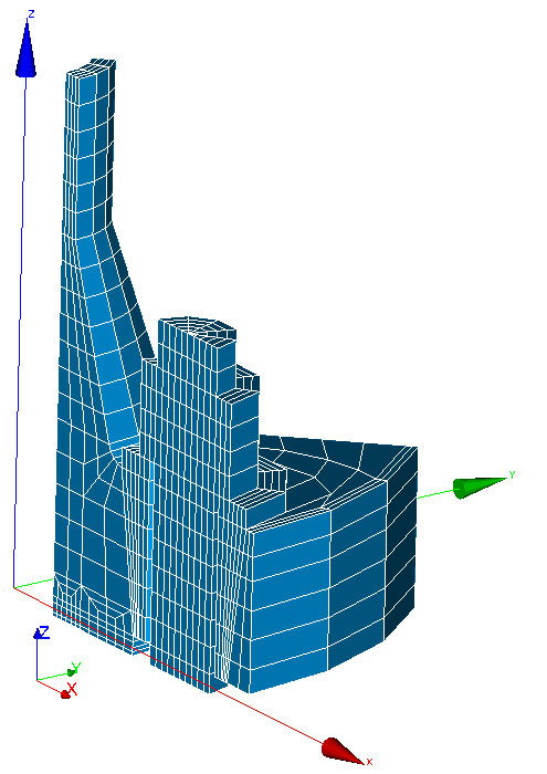
Figure 1.3-a: Flange and stud mesh.
1.4. Materials#
The material is elastic and its properties are: \(E\mathrm{=}200000\mathit{MPa}\) and \(\nu \mathrm{=}0.3\).
1.5. Boundary, contact and loading conditions#
The blocking boundary conditions are as follows:
blocking the degree of freedom DZ on the underside of the stud and the joint,
symmetry conditions by blocking the normal movement of the lateral face with bore,
symmetry conditions by blocking the normal movement of the lateral face without a bore,
condition of flatness of the cut face of the tube in plane \(\mathit{XY}\) by imposing an identical value for the degree of freedom DZ on all the nodes of the face,
tightening condition via a zero difference between the degrees of freedom DX and DY of the knots of the nut and the stud in relation to each other,
pressure of \(1.0E-06\mathit{Pa}\) inside the tube.
condition of contact between the faces of the joint and the flange.
The load corresponds to a relative displacement imposed on the nodes of the nut and the stud. It is zero at time zero and is DEPL_R at time \(1.0\).
Note:
The move is named DEPL_R in order to reuse the command file for modeling A directly with MACR_RECAL in modeling B. Indeed, the macro-command requires the presence of “__” at the end of the name of the parameters to be reset.
1.6. Modeling#
The modeling is 3D.
1.7. Effort sought#
The aim is to apply a displacement DEPL_R corresponding to an average stress of \(\mathrm{30 }\mathit{MPa}\) in the stud shaft, i.e. an effort resulting from:
\({F}^{\mathit{résultant}}\mathrm{=}{\sigma }^{\mathit{pré}\mathrm{-}\mathit{tension}}.\pi .{R}_{\mathit{goujon}}^{2}\mathrm{/}2\mathrm{=}\mathrm{1695.6N}\). Dividing by 2 takes symmetry into account.