3. Modeling B: in dimension 3#
In this modeling, we consider the structure in 3D.
3.1. Characteristics of the mesh#
The structure is modelled by a regular mesh composed of \(2\mathrm{\times }5\mathrm{\times }5\) HEXA8, respectively along the \(x,y,z\) [Figure 3.1-3.1-a] axes. The interface goes through the middle of the elements.
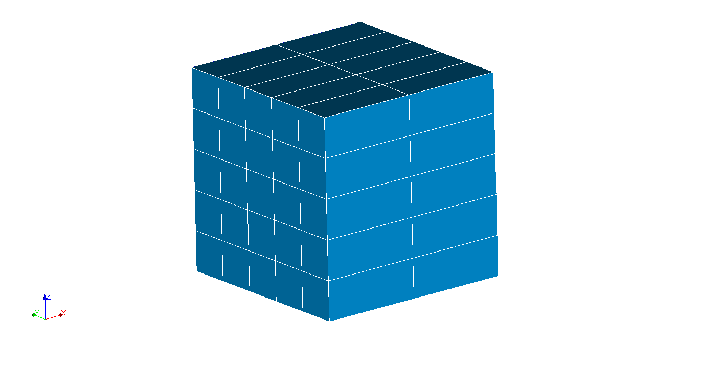
Figure 3.1‑ 3.1-a : 3d mesh
3.2. Tested features#
We test the application of Neumann conditions via the AFFE_CHAR_MECA and AFFE_CHAR_MECA_F commands on a non-meshed interface with X- FEM.
This imposition is done using the FISSURE keyword from the PRES_REP operand, because the interface is not a group of elements.
We test the application of a constant pressure using a real and then using a space function such as \(p\mathrm{=}y\mathrm{\times }20000\mathit{Pa}\) (the crack is in \(y\mathrm{=}0.5\) which is equivalent to applying a constant load).
3.3. Tested sizes and results#
The displacement values are tested after convergence of the iterations of the operator STAT_NON_LINE.
Identification |
Reference |
\(\mathit{DZ}\) for all nodes just below the interface |
-5,00E-7 |
\(\mathit{DZ}\) for all nodes just above the interface |
5,00E-7 |
To test all the nodes at once, we test the minimum and the maximum of the column.