3. Modeling A#
3.1. Characteristics of modeling#
We consider 3D modeling X- FEM with contact taking into account. The interface is introduced into the healthy mesh by the operator DEFI_FISS_XFEM.
3.2. Characteristics of the mesh#
We discretize the structure using finite elements HEXA8. According to the three directions of the chosen reference system, we have \(2\times 4\times 9\) elements so a total of 72 finite elements (see [])
The interface will be introduced in the middle of the fifth element floor along the \(\mathrm{OZ}\) direction.
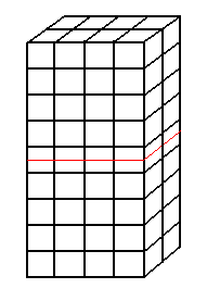
Figure 3.2-1: M**mesh of modeling A**
3.3. Tested sizes and results#
The POST_MAIL_XFEM operator makes it possible to mesh the cracks represented by the X- FEM method. The POST_CHAM_XFEM operator then makes it possible to export the X- FEM results to this new mesh. These two operators should only be used after the calculation in post-processing views. They allow nodes to be generated just below and above the interface and to show their movements.
We therefore test the values of the displacement just below and above the interface after convergence of the iterations of the operator STAT_NON_LINE. The following table is obtained:
No |
Identification |
Reference |
Tolerance |
1 |
|
0.00 |
1.0E-16 |
1 |
|
0.00 |
1.0E-16 |
1 |
|
0.00 |
1.0E-16 |
1 |
|
1.0E-03 |
1.0E -09% |
2 |
|
0.00 |
1.0E-16 |
2 |
|
0.00 |
1.0E-16 |
2 |
|
-5.0E-4 |
1.0E -09% |
2 |
|
-5.0E-4 |
1.0E -09% |
3 |
|
0.00 |
1.0E-16 |
3 |
|
1.0E-03 |
1.0E -09% |
3 |
|
5.0E-4 |
1.0E -09% |
3 |
|
5.0E-4 |
1.0E -09% |
To test all the nodes at once, we test the minimum and the maximum of the column