2. Modeling A#
In this modeling, for pressure loading, loading is applied using a constant distributed pressure or constant surface forces for load 1, and a distributed pressure or distributed forces functions of \(z\) for load 2.
In this modeling, for surface force loading, loading is applied using constant surface forces for load No. 1, and surface forces based on \(z\) for load No. 2.
2.1. Characteristics of the mesh#
The structure is meshed with hexahedra with 8 knots. The number of elements is as small as possible, i.e. one element along the \(\mathrm{Ox}\) axis, 2 elements along the \(\mathrm{Oy}\) axis (in order to be able to define the nodes in the middle plane at \(y=\mathrm{LY}/2\)), and 5 elements along the \(\mathrm{Oz}\) axis. Along the \(\mathrm{Oz}\) axis, the number of elements is odd so that the interface does not coincide with the faces of the elements; the 3 layers of central elements use X- FEM elements, and the 2 layers of elements at the top and bottom use conventional elements.
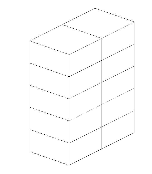
Figure 2.1-1 : 3D mesh
2.2. Features tested#
The PRES_REP keyword of the AFFE_CHAR_MECA [U4.44.01] operator makes it possible to apply a constant distributed pressure to skin elements. When pressure is a function or a formula, we use the PRES_REP keyword from AFFE_CHAR_MECA_F [U4.44.01]). This feature is tested with load #2. In fact, with X- FEM, you cannot define an upper and lower lateral surface as a group of elements. In the present case, a single group of elements comprising all the lateral surface cells is defined, and a pressure that is a function of \(z\) is applied to this group of elements.
The FORCE_FACE keyword of the AFFE_CHAR_MECA [U4.44.01] operator makes it possible to apply a constant surface force to skin elements. When surface strength is a function or a formula, we use the FORCE_FACE keyword from AFFE_CHAR_MECA_F [U4.44.01]).
2.3. Tested sizes and results#
The POST_MAIL_XFEM operator makes it possible to mesh the cracks represented by the X- FEM method. The operator POST_CHAM_XFEM then makes it possible to export the results X- FEM to this new mesh. These two operators should only be used after the calculation in post-processing views. They allow nodes to be generated just below and above the interface and to show their movements.
For each lateral face of the structure (\(y=0\) and \(y=\mathrm{LY}\)), we test the movements of the nodes located just above and just below the level set.
2.3.1. Compression loading (pressure loading)#
Identification |
Reference |
\(\mathrm{DY}\) for all nodes on the left surface located just below the interface |
10-6 |
\(\mathrm{DY}\) for all nodes on the left surface located just above the interface |
10-6 |
\(\mathrm{DY}\) for all nodes on the right surface located just below the interface |
-10-6 |
\(\mathrm{DY}\) for all nodes on the right surface located just above the interface |
-10-6 |
2.3.2. Compression loading/traction (pressure loading)#
Identification |
Reference |
\(\mathrm{DY}\) for all nodes on the left surface located just below the interface |
-10-6 |
\(\mathrm{DY}\) for all nodes on the left surface located just above the interface |
10-6 |
\(\mathrm{DY}\) for all nodes on the right surface located just below the interface |
10-6 |
\(\mathrm{DY}\) for all nodes on the right surface located just above the interface |
-10-6 |
2.3.3. Compression loading (surface force loading)#
Identification |
Reference |
\(\mathrm{DY}\) for all nodes on the left surface located just below the interface |
10-6 |
\(\mathrm{DY}\) for all nodes on the left surface located just above the interface |
10-6 |
\(\mathrm{DY}\) for all nodes on the right surface located just below the interface |
-10-6 |
\(\mathrm{DY}\) for all nodes on the right surface located just above the interface |
-10-6 |
2.3.4. Compression/tensile loading (surface force loading)#
Identification |
Reference |
\(\mathrm{DY}\) for all nodes on the left surface located just below the interface |
-10-6 |
\(\mathrm{DY}\) for all nodes on the left surface located just above the interface |
10-6 |
\(\mathrm{DY}\) for all nodes on the right surface located just below the interface |
10-6 |
\(\mathrm{DY}\) for all nodes on the right surface located just above the interface |
-10-6 |
To test all the nodes at once, we test the minimum and the maximum of the column.