1. Reference problem#
1.1. Geometry#
The structure is a straight parallelepiped with a square and healthy base. The dimensions of the block (see [Figure -1.1-a]) are: \(\mathrm{LX}=5m\), \(\mathrm{LY}=20m\), and \(\mathrm{LZ}=20m\). It has no cracks.
The interface is introduced by level sets directly into the command file using the DEFI_FISS_XFEM [U4.82.08] operator. The interface is present in the middle of the structure through its representation by the level sets. The normal level set (\(\mathrm{LSN}\)) allows you to define a plane interface making an angle \(\theta\) with the plane \(\mathrm{Oxy}\) by the following equation:
\(\mathrm{LSN}=Z-(\mathrm{aY}+b)\) eq 1.1-1
where \(a\) is the slope of the interface, which is \(a\mathrm{=}\mathrm{-}\mathrm{tan}(\theta )\) and \(b=\frac{\mathrm{LZ}}{2}-a\frac{\mathrm{LY}}{2}\).

Figure - 1.1-a : Bar geometry and interface position
In \(\mathrm{2D}\), we have an equivalent structure.

Figure 1.1-b : Geometry and positioning of the interface in \(\mathrm{2D}\)
1.2. Material properties#
Young’s module: \(E=100\mathrm{MPa}\)
Poisson’s ratio: \(\nu =0\).
1.3. Boundary conditions and loads#
The nodes on the lower face of the bar are embedded and a displacement \(\mathrm{UZ}=-{10}^{-6}m\) is imposed on those on the upper face which corresponds to a loading under pressure along the axis \(z\). Displacements along the \(x\) and \(y\) axes are blocked for the nodes on the upper surface. In \(\mathrm{2D}\), the movement is carried out along the \(y\) axis.
1.4. Characteristics of the mesh#
The structure is modelled in \(\mathrm{3D}\) by a regular mesh composed of \(5\times 20\times 20\) HEXA8 [Figure 1.4-a].
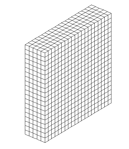
Figure - 1.4-a : Mesh \(\mathrm{3D}\)
This mesh is composed of linear finite elements. However, as part of the continuous [bib1] method with X- FEM [bib2], it is necessary to switch to linear elements that are a bit special. These elements have linear form functions and a quadratic support mesh. On these elements, the vertex nodes carry the unknowns of the displacement, and the middle nodes carry the unknowns related to the contact. In addition, when the interface follows the border of an element, the element’s vertex nodes also carry contact unknowns.
For test cases \(\mathrm{2D}\), the structure is modelled by a regular mesh composed of \(20\times 20\) QUAD4.

Figure - 1.4-b : Mesh \(\mathrm{2D}\)
1.5. Bibliography#
MASSIN P., BEN DHIA H., ZARROUG M.: Contact elements derived from a continuous hybrid formulation, Code_Aster Reference Manual, [R5.03.52]
MASSIN P., GENIAUT S.: Method X- FEM, Code_Aster Reference Manual, [R7.02.12]
TARDIEU N., VAUTIER I., LORENTZ E.: Quasi-static Nonlinear Algorithm, Code_Aster Reference Manual, [R5.03.01]
DHATT G., TOUZOT G.: A presentation of the finite element method, Maloine Ed., PARIS