1. Reference problem#
1.1. Geometry#
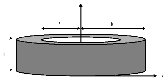
The cylinder has an inner radius \(a=10m\), an outer radius \(b=20m\), a height of \(h=\mathrm{0.02m}\)
The circumferential frame, positioned on the outside surface of the cylinder, has a cross section per unit length of \(s\mathrm{=}0.1{m}^{2}\mathrm{/}\mathit{ml}\). The main direction of the reinforcements is vertical.
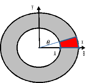
Only a portion of the cylinder, corresponding to an angular section \(\theta ={0.1}^{°}\), is modelled.
1.2. Material properties#
The material characteristics of the concrete forming the hollow cylinder are:
\(E=20000\mathrm{MPa}\), \(\nu =0.2\)
The material characteristics of the frames are:
\(E=200000\mathrm{MPa}\), \(\nu =0.0\), \({\sigma }_{y}=200000\mathrm{MPa}\), \({E}_{\mathrm{cr}}=20000\mathrm{MPa}\)
To model reinforcement grids, we use RELATION =” GRILLE_ISOT_LINE “in the stat_non_line command. To do this, the behavior assigned to reinforcement grids must define the plastic characteristics. In all models the behavior of steels must remain in the elastic domain, \({\sigma }_{y}\) is given large enough to meet this condition.
1.3. Boundary conditions and loads#
The following boundary conditions are imposed on the modelled angular section:
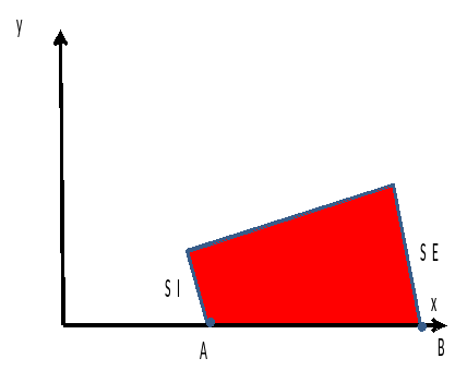
zero displacement on the lower surface of the cylinder
zero normal displacement on the lateral faces of the cylinder section
The load consists of an imposed pressure \({10}^{6}\mathrm{Pa}\) on the internal surface \(\mathit{SI}\) of the cylinder section.
1.4. Initial conditions#
Initially, travel and constraints were zero everywhere.