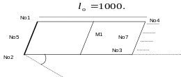
1. Reference problem#
1.1. Geometry#
The geometry for this test is a square plate in plane \((x,y)\) rotated \(30°\) with respect to \(x\) around \(z\).

Z
Y
X
We call
the length of the deformed plate, we will note \(x,y,z\) the coordinates of the deformed configuration and \(X,Y,Z\) the coordinates of the initial configuration
1.2. Material properties#
We take
1.3. Boundary conditions and mechanical loads#
We block nodes \(\mathit{No1}\), \(\mathit{No5}\), and \(\mathit{No2}\) so that \(\mathit{DX}\mathrm{=}\mathit{DY}\mathrm{=}\mathit{DZ}\mathrm{=}\mathit{DRX}\mathrm{=}\mathit{DRY}\mathrm{=}\mathit{DRZ}\mathrm{=}0\),
and a local displacement \(\mathit{Dx}\mathrm{=}100.\) is imposed on the nodes \(\mathit{No3}\), \(\mathit{No4}\) and \(\mathit{No7}\).