3. Modeling A#
3.1. Characteristics of modeling#
This is a FEM model, in plane deformations. The three blocks are meshed with compliant meshes and the contact conditions are imposed on the edges of these blocks. The master edges on the middle block and the slave edges on the lower and upper blocks are declared in order to comply with [Figure 1.3-1].
3.2. Characteristics of the mesh#
The mesh is adjusted (see []) and includes 3 blocks composed of QUAD4 meshes. The 3 blocks each have 256 stitches.
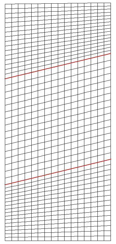
Figure 3.2-1: The modeling A mesh
3.3. Tested sizes and results#
The contact pressures on the upper lip of the lower block, the latter being declared a slave, are tested at the end of each load step in question. The location of the nodes that store the contact degrees of freedom, whose values are tested, is illustrated on the [].
No |
Identification |
Reference |
Tolerance |
LAGS_C for N10 |
0.0000000E+00 |
1.0E-12 |
|
LAGS_C for N60 |
-6.3355792D+04 |
|
|
1 |
|
-6.0652836D+04 |
|
LAGS_C for N52 |
-5.0757743D+04 |
|
|
LAGS_C for N9 |
0.0000000E+00 |
1.0E-12 |
|
LAGS_C for N10 |
0.0000000E+00 |
1.0E-12 |
|
LAGS_C for N60 |
-1.8115145E+05 |
|
|
2 |
|
-1.2479791E+05 |
|
LAGS_C for N52 |
-1.0307176E+05 |
|
|
LAGS_C for N9 |
0.0000000E+00 |
1.0E-12 |
|
LAGS_C for N10 |
0.0000000E+00 |
1.0E-12 |
|
LAGS_C for N60 |
0.0000000E+00 |
1.0E-12 |
|
3 |
|
-2.0163278E+05 |
|
LAGS_C for N52 |
-1.5784447E+05 |
|
|
LAGS_C for N9 |
0.0000000E+00 |
1.0E-12 |
|
LAGS_C for N10 |
0.0000000E+00 |
1.0E-12 |
|
LAGS_C for N60 |
0.0000000E+00 |
1.0E-12 |
|
4 |
|
-3.7985867E+05 |
|
LAGS_C for N52 |
-2.2011907E+05 |
|
|
LAGS_C for N9 |
0.0000000E+00 |
1.0E-12 |
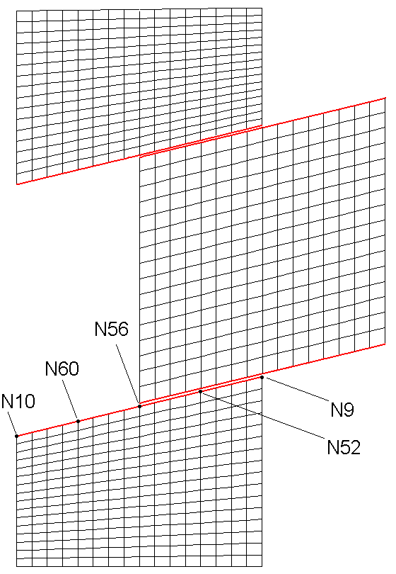
Figure 3.3-1: The location of the nodes that store the tested contact degrees of freedom