1. Reference problem#
1.1. Geometry and loading#
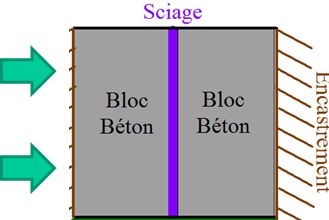
We consider two dam blocks, represented by regular cubes of length \(L=\mathrm{5m}\), height \(H=\mathrm{10m}\) and depth \(P=\mathrm{1m}\). The distance between the pads is assumed to be non-zero to simplify the generation of the joint mesh (\(\epsilon =\mathrm{1mm}\)). The embedding varies according to the models.
1.1.1. A, B, E, F, G, H models#
The lower parts of the studs are embedded. The studs are subject to their gravitational weights. Charging takes place in two steps:
The pads balance under the gravitational load. The joint opens in the upper part because of the compression of the lower parts of the studs. One of the two industrial procedures is then applied:
The locking procedure is activated: « the concrete is injected » between the studs at PRES_CLAVAGE = \(5{10}^{4}\mathit{Pa}\). The joint thickness profile is then modified so as to obtain the claving pressure on the lips of the crack. It is this profile that is then stored by one of the internal variables to « memorize » the quantity of injected concrete.
The sawing procedure is activated via the keyword SCIAGE. The thickness of saw \({\delta }_{\mathit{scie}}\) is selected so that the top part of the stud is only partially sawn off.
Drawing 1: Diagram of dam blocks, boundary conditions and loading
1.1.2. C, D models#
The left side of the stud is embedded, while an imposed displacement is applied to the right side of the stud. The sawing procedure is then activated via the keyword SCIAGE. The thickness of saw \({\delta }_{\mathit{scie}}\) is selected so that the joint is only partially sawn.
Drawing 2: C and D models, which allow the theoretical validation of sawing
1.2. Material properties#
The values of the mechanical parameters of the studs (Young’s modulus, Poisson’s ratio, volume density) are chosen in the following way:
\(E={3.10}^{2}\mathit{Pa}\) |
|
|
The saw thickness varies according to the modeling.
1.2.1. Material JOINT_MECA_RUPT#
For the joint, the normal stiffness is taken to be equal to the tangential stiffness. There is no tensile strength. The coupling between the normal opening and the tangential stiffness is chosen so as to have the tangential slope zero as soon as the joint reaches the complete normal damage threshold. The softening slope at break is five times steeper than the normal loading slope (see document R7.01.25). After mechanical gravitational loading, one claves at a non-zero claving pressure:
\({K}_{N}={K}_{T}={10}^{12}\mathit{Pa}/m\) |
|
|
\(\alpha =1\) |
|
|
(NB: « test » values that do not correspond to any particular material)
1.2.2. Material JOINT_MECA_FROT#
For the law of friction associated with the joint, « test » values are chosen that do not correspond to any particular material.
\({K}_{N}={K}_{T}/2={10}^{12}\mathit{Pa}/m\) |
|
|
\(\mu =0.35\) |
|
|