1. Reference problem#
1.1. Geometry#
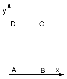
Point coordinates |
\(X\) |
|
\(A\) |
0 |
0 |
\(B\) |
0.5 |
0 |
\(C\) |
0.5 |
1.0 |
\(D\) |
0 |
1,0 |
The geometry is rectangular in shape.
1.2. Material properties#
For modeling A, the mass consists of an elasto-plastic material with linear negative work-hardening.
For modeling B, the mass consists of an elasto-plastic material with parabolic negative work hardening.
The elastic parameters of the material are as follows:
Young’s module: \(E=5800\mathrm{MPa}\)
Poisson’s ratio: \(\nu =\mathrm{0,3}\)
Real constant density: \(\rho \mathrm{=}2764\)
Isotropic thermal expansion coefficient: \(\alpha =0\)
The characteristics of work hardening are then given by:
Pressure dependence coefficient: \(\alpha =\mathrm{0,33}\)
Ultimate cumulative plastic deformation: \({P}_{\mathrm{ULT}}=\mathrm{0,01}\)
Elastic limit: \({\sigma }_{y}\mathrm{=}2.11{10}^{6}\)
Elastic limit for the mesh concerned: \({\sigma }_{y}\mathrm{=}2.\mathrm{\times }{10}^{6}\)
For modeling A:
Work hardening module for the entire mesh: \(H\mathrm{=}\mathrm{-}200.\mathrm{\times }{10}^{6}\)
For modeling B:
Ultimate constraint: \({\sigma }_{\mathit{yULT}}\mathrm{=}0.47\mathrm{\times }{10}^{6}\)
Ultimate constraint for the mesh concerned: \({\sigma }_{\mathit{yULT}}\mathrm{=}0.44\mathrm{\times }{10}^{6}\)
1.3. Boundary conditions and loads#
A drained biaxial test (D_ PLAN) is modelled. The trips normal to the study plan are therefore zero. A vertical displacement is imposed on \(\mathrm{[}\mathit{DC}\mathrm{]}\) while maintaining the constant lateral pressure (\(2\mathit{MPa}\)) in the study design. The boundary conditions are therefore as follows:
\({u}_{y}\mathrm{=}0\) out of \(\mathrm{[}\mathit{AB}\mathrm{]}\) (mesh group \(\mathit{BAS}\))
\({u}_{x}\mathrm{=}0\) out of \(\mathrm{[}\mathit{AD}\mathrm{]}\) (mesh group \(\mathit{GAUCHE}\))
\({\sigma }_{n}\mathrm{=}2.\mathrm{\times }{10}^{6}\) out of \(\mathrm{[}\mathit{BC}\mathrm{]}\) (mesh group \(\mathit{EXTREM}\))
A vertical displacement is then imposed on \(\mathrm{[}\mathit{DC}\mathrm{]}\) (mesh group \(\mathit{HAUT}\)) to apply vertical deformation up to \(\text{3\%}\).
1.4. Results#
The solutions are post-treated in order to control the evolution of the quantities of INDL_ELGA and PDIL_ELGA in non-regression.