1. Reference problem#
1.1. Geometry#
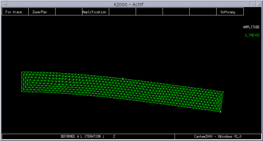
Figure 1.1-a: Deformed mesh

Figure 1.1-b: Diagram of thermal loads and geometry
It is a metal beam (steel 1 6MND5, \(E={210.10}^{3}\mathrm{Mpa}\), \(\nu =0.2\)) in bending. Elastic calculation (MECA_STATIQUE or STAT_NON_LINE) in plane stress modeling (C_PLAN). Meshes in TRIA3/SEG2 (modeling A) and TRIA6/SEG3 (models B and C).
The various key areas of the calculation are designated: GM14 for the entire volume part in TRIA, GM13 for the embedment (DDL_IMPO DX=DY=0 for all points \((X=\mathrm{0,}Y=0\dots 10)\)), GM12 for the distributed pressure (PRES_REP =0.1N for all points \((X=50\dots \mathrm{100,}Y=10)\)) and GM10 (mesh-point) \(\mathrm{M1}=\mathrm{N2}\) at the point \((X=\mathrm{100,}Y=0)\) where we will measure the arrow).
1.2. Material properties#
Material characteristics are applied throughout the structure (GROUP_MA GM14)

1.3. Boundary conditions and loads#
The breakdown of loads by zone can be summarised in the form of the following table:
Loads |
|
GM13 |
DX=0, DY=0 |
GM12 |
|