3. Modeling A#
3.1. Characteristics of modeling#
This is an elastoplasticity calculation under the hypothesis of small displacements, under plane stresses.
3.2. Characteristics of the mesh#
The mesh, built with an automatic gibi procedure, consists of 400 quadratic elements (1000 nodes). Toros are defined at the bottom of the crack in order to improve the accuracy of the calculation in fracture mechanics, see [Figure 3.2-a] below. The radius of the largest torus is \(\mathrm{1,5 }\mathrm{mm}\).
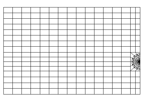
Figure 3.2-a: Cracked rectangular plate mesh
3.3. Tested sizes and results#
The values of the return rate are tested for five values of the imposed horizontal displacement \(\delta\). The results obtained for three different integration rings are compared:
Imposed move \(\delta\) ( \(\mathrm{mm}\) ) |
\(G(N/\mathrm{mm})\) crown 1 |
\(G(N/\mathrm{mm})\) crown 2 |
\(G(N/\mathrm{mm})\) crown 3 |
0.02 |
3.29 |
3.20 |
3.20 |
0.04 |
13.60 |
13.24 |
13.24 |
0.06 |
31.97 |
31.22 |
31.24 |
0.08 |
58.99 |
57.74 |
57.76 |
0.1 |
91.42 |
89.64 |
89.71 |
The results are satisfactory: the maximum difference between the values of \(G\) obtained on the three integration rings is less than \(\text{2 \%}\).