1. Reference problem#
1.1. Geometry#
This non-regression test case represents a three-point test of a thick beam. The beam is represented by a rectangular element 7.5 meters long and 4.7 meters high. The element contains a square hopper with a side of 1.5 meters located according to Figure 1.1.-a. A fixed support is placed at the left end of the base of the element and a vertical support is considered to be placed at the right end. A vertical load equal to 3 MN is applied in the direction of gravity at 4.7 meters from the left edge. The geometry, boundary conditions, and material definitions were taken directly from the reference [Shlaich et al., 1987].
P=3 MIN
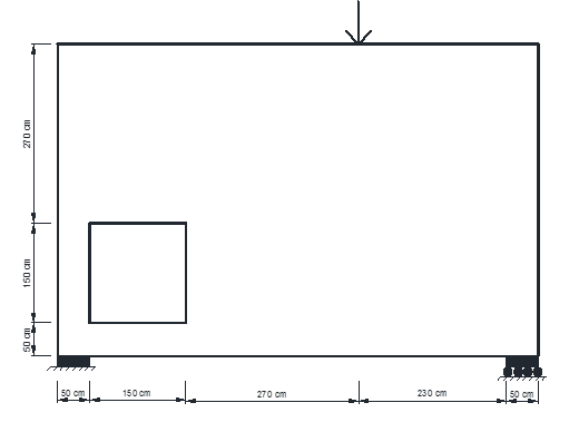
Image 1.1-1: Sail girder with hopper
1.2. Materials#
The reinforced concrete used for plane modeling corresponds to a linear elastic material with the following characteristics:
Concrete:
Young’s modulus |
\(E\) |
21 GPa |
Poisson’s Ratio |
\(\nu\) |
0.2 |
Elastic limit |
\({f}_{\mathit{cm}}\) |
36 MPa |
Table 1.2-1
Reinforcing steel:
Young’s modulus |
\(E\) |
210 GPa |
Elastic limit |
\({f}_{y}\) |
500 MPa |
Table 1.2-2
1.3. Boundary conditions and loading#
The beam is assumed to have a fixed support at the level of the left side and a carriage-type support (locked in the vertical direction) at the level of the level of the right side. The load and boundary conditions are taken as shown in Figure 1.1-1.
1.4. Characteristics of the mesh#
Number of knots: 13504
Number of meshes and types: 13200 meshes QUAD4
1.5. Benchmark solution#
1.5.1. Diagram of the Bielles-Tirants truss#
One of the solutions proposed in reference [Schlaich et al., 1987] is shown in Figure 2.1-a. The author approaches the problem via an ad hoc definition of the Bielles-Tirants model.
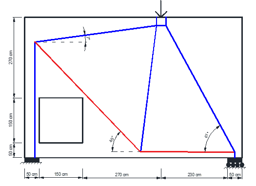
Figure 1.5-1: BT reference model [Shclaich et al., 1987]
1.5.2. Benchmark results#
The tie rod sections are shown in the following table:
Pulling |
Knot i |
Knot j |
Force [MN] |
Length [m] * |
As [m2]* |
|
T2 |
5 |
6 |
1.33 |
1.33 |
5.6 |
0.0024 |
T1 |
0 |
5 |
1.07 |
1.07 |
3 |
0.0027 |
Table 1.5-1: Tie rod sections [Shclaich et al. 1897]