1. Reference problem#

1.1 Geometry
As shown in Figure 1, the structure under investigation is a 2D plate containing a centrally placed crack. The crack is subjected to tensile loading conditions in the presence of initial stress fields.
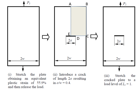
Figure 1: Geometry description.
The geometry parameters of this rectangular plate are a width, 2w = 50 mm, a height, 2h = 140 mm, and a crack length with the ratio a/w = 0.4.
Figure 1 also describes the shows the analysis sequence, which is split into three steps:
Step 1: Uncracked plate is stretched beyond yielding until an equivalent plastic strain of 55.9% is achieved before the load is released. This generates an initial stress field.
Step 2: A crack is introduced into the middle of the plate, and a dummy step run in order to produce an auto-equilibriated stress state in the plate.
Step 3: The cracked plate is loaded again to 0.2% proof stress, thereby achieving a load lever Lr = 1.
1.2 Material Properties
For code_aster model to compute initial stress, the material is elastoplastic of Von Mises with a bi-linear strain-stress relationship
Young modulus E = 500 MPa
Plastic modulus Ep = (-y) /p
Elastic limit y = 1 MPa
E/Ep = 500
Fish’s ratio = 0.3
1.3 Boundary conditions and loading
Thanks to symmetry, a quarter scale symmetric model of the geometry is considered, ABCDE (see Figure 1-ii). The boundary conditions applied to the different sides of the geometry during each step are shown below:
Step 1:
AE: UX = 0
FROM: UY = 0
CD: UY=0
AB: P1 = -1.8 MPa
Step 2:
AE: UX = 0
CD: UY=0
Step 3:
AE: UX = 0
CD: UY=0
AB: P2 = -0.7 MPa
The stress obtained at the end of step 2 is introduced into step 3 as the initial stress.