2. Modeling#
2.1. TP implementation#
2.1.1. Creation of meshes#
Beam mesh (15 to 20 elements).
Meshing the right section of the beam (20 to 25 elements in the height, 2 to 5 elements in the width).
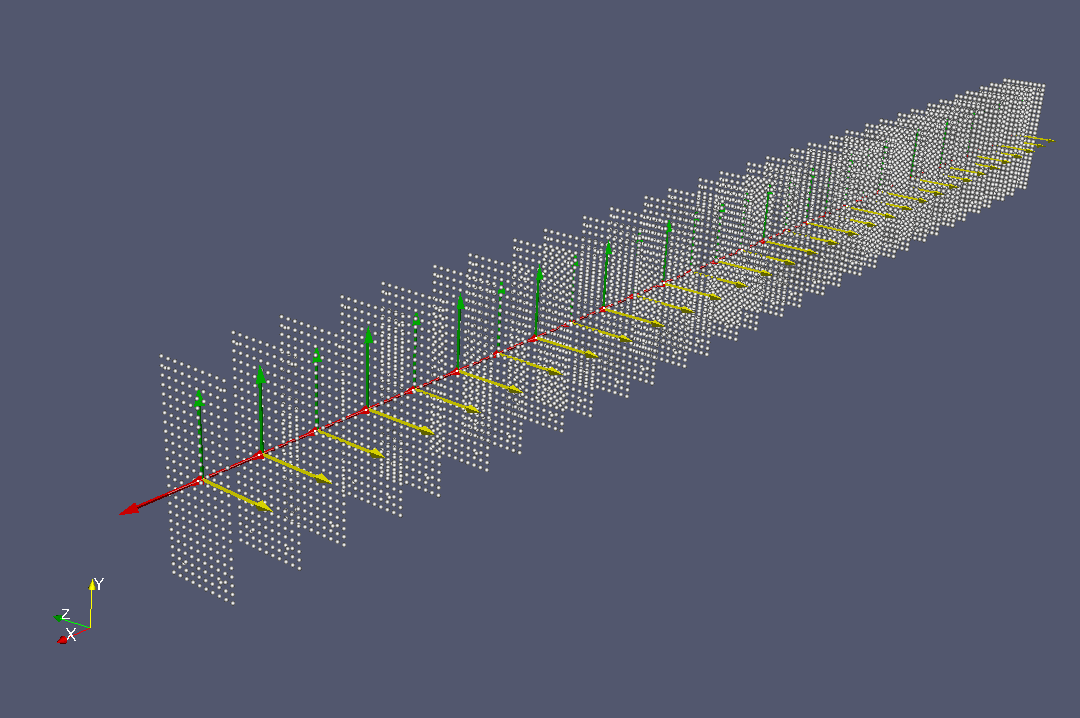
2.1.2. Definition of fibers#
Use the DEFI_GEOM_FIBRE [U4.26.01] command to define the multi-fiber cross section of the beam.
Visualization of the fiber section with CREA_MAILLAGE [U4.23.02].
2.1.3. Definition of materials#
Define materials using command DEFI_MATER_GC [U4.42.07].
2.1.4. Data checks#
Visualize the right section of the multifiber beam with local landmarks.
2.1.5. Calculus#
Conduct the calculation as far as possible.
2.1.6. Post-treatments#
Support reaction according to the arrow in the center
Changes in deformations:
Deformations of stretched and compressed concrete.
Deformations of tense and compressed steels.
Changes in constraints:
Constraints of stretched and compressed concrete.
Stresses of stretched and compressed steels.
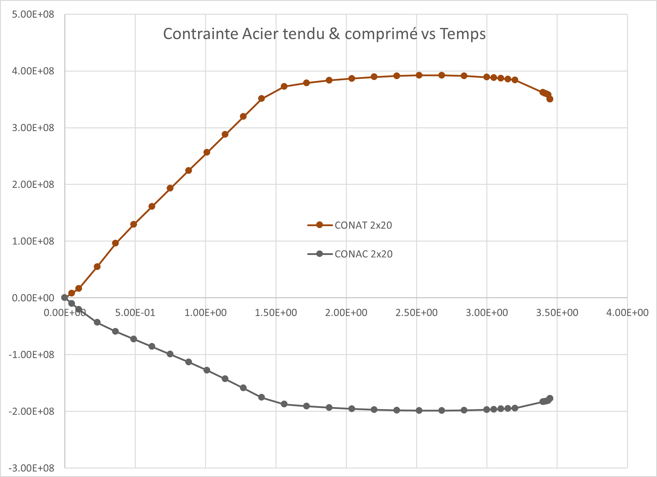
Figure 2.1.6-a :Changes in stresses in steels as a function of time.
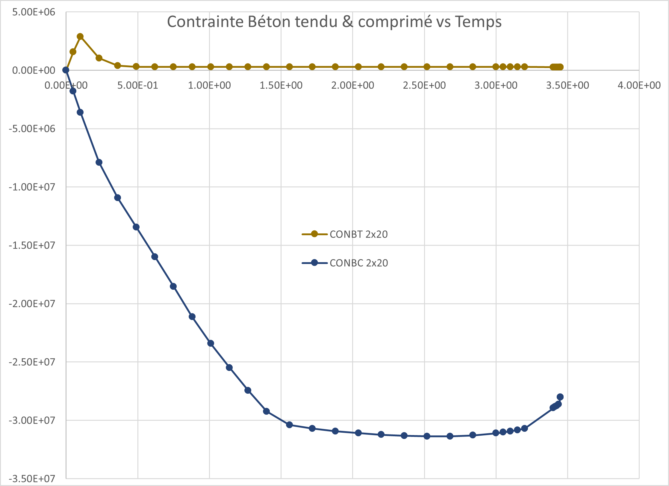
Figure 2.1.6-b :: ** Changes in stresses in concrete as a function of time.
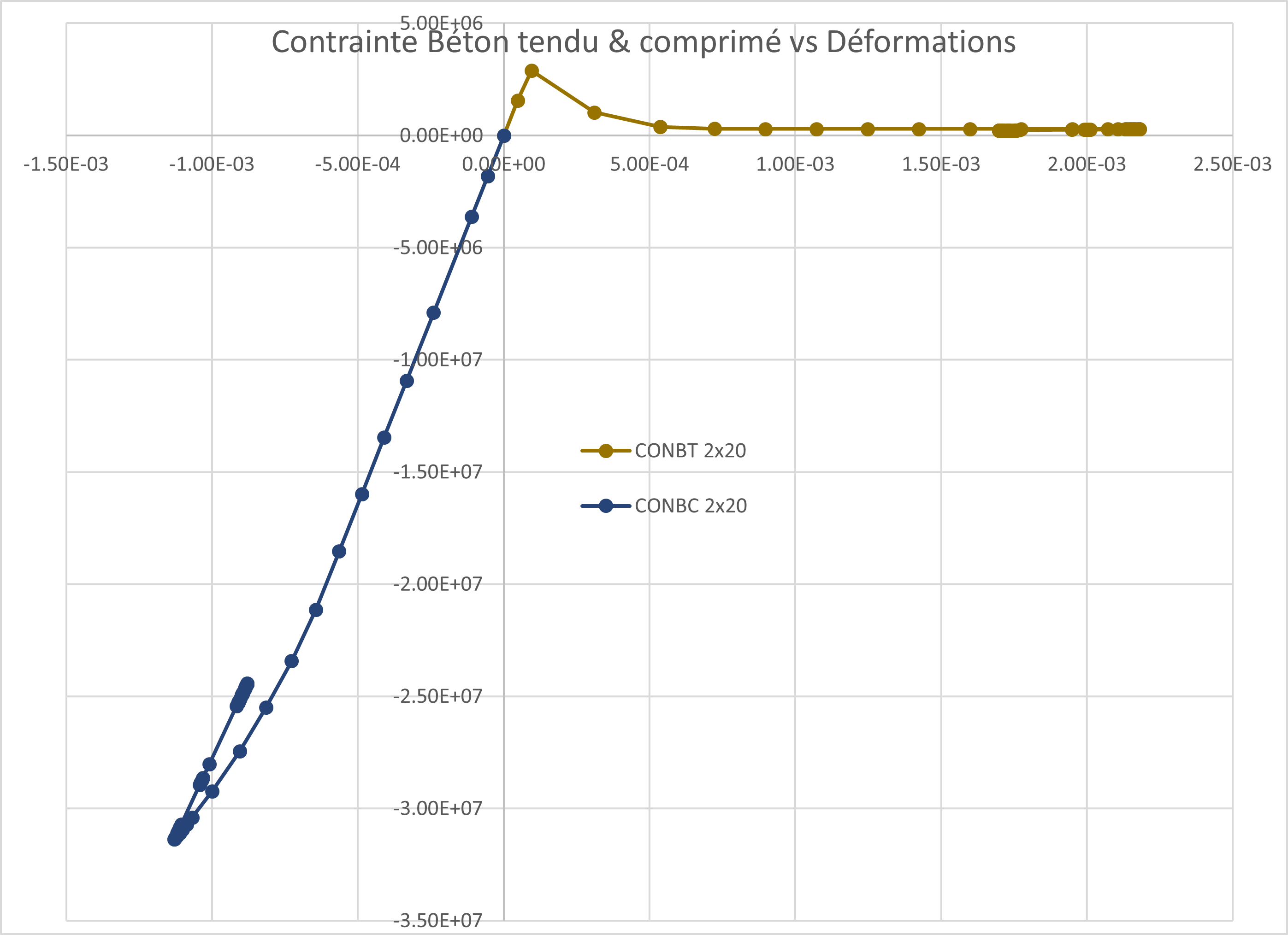
Figure 2.1.6-c : Changes in stresses in concrete as a function of deformations.
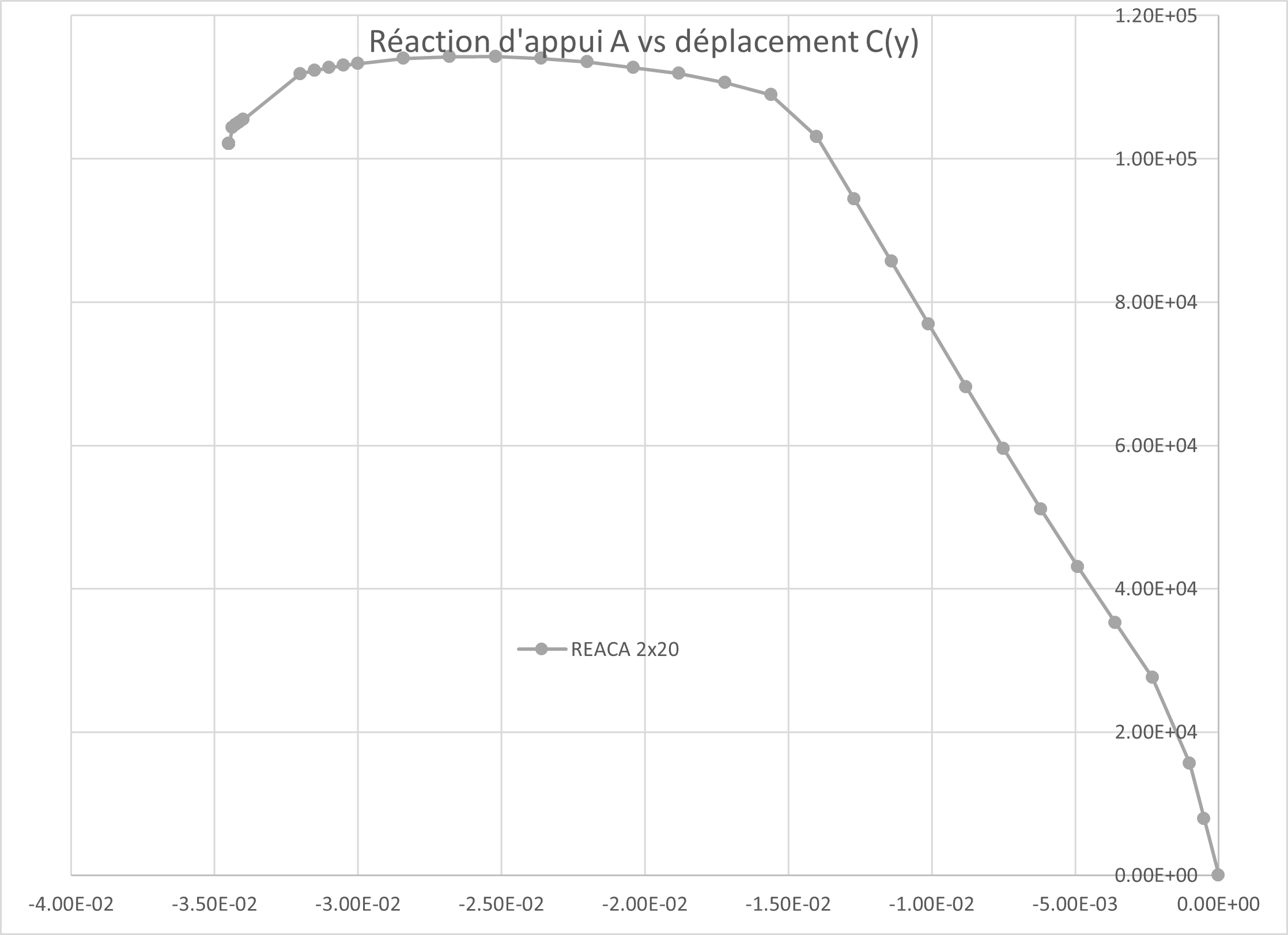
Figure 2.1.6-d :: ** Changes in the support reaction as a function of the arrow.