3. Modeling A#
3.1. Characteristics of modeling#
Modeling POU_D_TGM
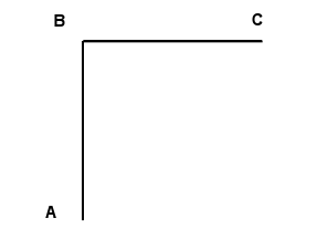
Breakdown: 10 elements in the column and in the beam
3.2. Characteristics of the mesh#
Number of knots: 21
Number of meshes and types: 20 SEG2
3.3. Characteristics of the cross section mesh#
Number of fibers: 100 (divided into 10 on each side)
Number of meshes and types: 100 QUAD4
3.4. Tested sizes and results#
The results are obtained by an automatic division of the time step and with arc-length control of the overall displacement response of the structure.
Movement |
Identification |
Reference |
Reference Type |
Tolerance |
1.773 |
DX |
0.968 |
“SOURCE_EXTERNE” |
5% |
10.246 |
DY |
0.968 |
“SOURCE_EXTERNE” |
5% |
3.6975 |
DX |
1.242 |
“SOURCE_EXTERNE” |
5% |
16.1245 |
DY |
1.242 |
“SOURCE_EXTERNE” |
5% |
6.496 |
DX |
1.4153 |
“SOURCE_EXTERNE” |
5% |
22.8245 |
DY |
1.4153 |
“SOURCE_EXTERNE” |
5% |
13.176 |
DX |
1.507 |
“SOURCE_EXTERNE” |
5% |
37.6525 |
DY |
1.507 |
“SOURCE_EXTERNE” |
5% |
18.5865 |
DX |
1.4605 |
“SOURCE_EXTERNE” |
5% |
43,3615 |
DY |
1,4605 |
“SOURCE_EXTERNE” |
5% |
23.085 |
X |
1.4006 |
“SOURCE_EXTERNE” |
5% |
48,318 |
DY |
1,4006 |
“SOURCE_EXTERNE” |
5% |
28.6505 |
DX |
1.3151 |
“SOURCE_EXTERNE” |
5% |
52,057 |
DY |
1.3151 |
“SOURCE_EXTERNE” |
5% |
38.5155 |
DX |
1.1062 |
“SOURCE_EXTERNE” |
5% |
57.5425 |
DY |
1.1062 |
“SOURCE_EXTERNE” |
15% |
45.851 |
DX |
0.9275 |
“SOURCE_EXTERNE” |
5% |
60.1085 |
DY |
0.9275 |
“SOURCE_EXTERNE” |
55% |
3.5. notes#
Using the arc-length technique makes it difficult to define the reference value to be entered in the TEST_RESU command, since these values cannot be imposed. The tests were therefore done in reverse by choosing the displacement values as a parameter and the force value as the tested value (i.e. ETA_PILOTAGE).
It is this way of testing that explains the high differences observed in \(\mathit{DY}\) at the last moments when the curves are superimposed perfectly.