1. Reference problem#
1.1. Geometry#
\(O\) |
|
|
|
|
||
\(x\) |
||||||
\(z\) |
Table 1.1-a : Coordinates of points (en \(m\) )
Names and positions of the nodes (middle of range before installation):
left hand range: \(\mathrm{N6}\) and \(x=48.50m\)
right-hand range: \(\mathrm{N19}\) and \(x=160.50m\)
1.2. Material properties#
Cable linear weight: \(30N/m\)
Axial stiffness of the cable (product of Young’s modulus by the area of the straight section): \(5\mathrm{.}{10}^{7}N\)
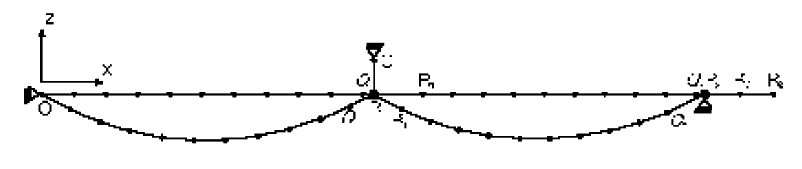
1.3. Boundary conditions and loads#
Points \(O\), \(C\), and \({P}_{2}\) are fixed.
The cable, fixed in \(O\), is supported by two pulleys. The first is attached to the lower end \({P}_{1}\) of the suspension attached in \(C\). The second is set to \({P}_{2}\).
The cable is subjected to its weight and is given an arrow by moving its right end from \(\mathrm{10 }m\) from \({R}_{2}\) to \({R}_{2}\text{'}\).
The position of points \({Q}_{1}\), \({R}_{1}\) and \({Q}_{2}\) is not imposed, but care must be taken to ensure that during installation the pulley \({P}_{1}\) stays on the cable section \({Q}_{1}{R}_{1}\).