1. Reference problem#
The objective of this test case is to validate the 3D gyroscopic modeling of a rotor (options MECA_GYRO and RIGI_ROTA) in Code_Aster.
The results obtained by modeling Code_Aster are compared with those obtained in ANSYS.
1.1. Geometry#
Consider the rotor shown in the diagram below. It is a shaft of length 0.3454 m and of variable cross section, supported on two bearings located respectively at positions 0.1651 m (level 1) and 0.287 m (level 2). The rotor has a disk with an internal radius 0.0203 m and an external radius of 0.0495 m (thickness 0.028 m).
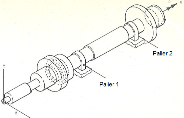
Image 1.1-1: Rotor geometry
1.2. Material properties#
The cylinder has a density of \(\rho \mathrm{=}7800\mathit{kg}\mathrm{/}{m}^{3}\).
The Young’s modulus is \(E\mathrm{=}207.{10}^{9}N{m}^{\mathrm{-}2}\) and the Poisson’s ratio is \(\nu \mathrm{=}\mathrm{0,3}\).
1.3. Boundary conditions and loads#
The shaft is based on two bearings (Stage 1 and Stage 2) having the following stiffness characteristics:
Setup A: Kxx = Kyy = 4.378x10⁷N/m, Kxy = Kyx = 0
Configuration B: Kxx = Kyy = 3.503x10⁷N/m, Kxy = Kyx = -8.756 x10⁶
It is stationary or rotating at a speed of 100,000 rpm.