3. Modeling A#
3.1. Characteristics of modeling#
The rotor is modelled by quadratic volume elements (PENTA15 and HEXA20). It is based on two levels having the characteristics given by configuration A above.
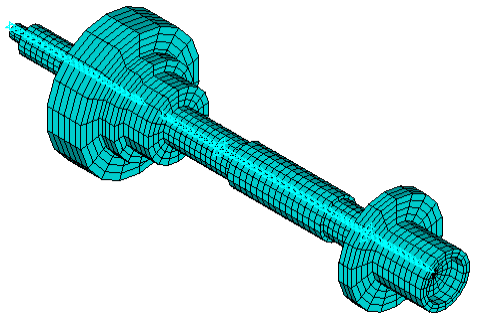
Image 3.1-1: Rotor mesh
CALC_MODES calculates the modes specific to standstill (ie. without gyroscopic damping) and at several speeds of rotation, i.e. with gyroscopic damping (option MECA_GYRO), but not taking into account the softening effect caused by centrifugal stiffness (option RIGI_ROTA).
3.2. Characteristics of the mesh#
Number of stitches HEXA8 |
4230 |
Number of stitches PENTA6 |
1386 |
Number of stitches DIS_T |
2 |
Table 3.2-1
3.3. Results: comparison between Code_Aster and ANSYS calculations#
For information purposes, the results of the rotating machine when stopped are given below.
Identification |
Reference type |
Reference value |
Tolerance |
Mode 1 |
“EXTERNE” |
416.38 |
|
Mode 2 |
“EXTERNE” |
416.38 |
|
Mode 3 |
“EXTERNE” |
772.65 |
|
Mode 4 |
“EXTERNE” |
772.65 |
|
Mode 5 |
“EXTERNE” |
1344.3 |
|
Mode 6 |
“EXTERNE” |
1344.3 |
|
Table 3.3-1 : Summary of standstill results
The tables below give the numerical values tested in this test case. These are the frequencies specific to 100,000 rpm of the rotor supported on its two bearings.
Identification |
Reference type |
Reference value |
Tolerance |
Mode 1 |
“EXTERNE” |
52.23 |
|
Mode 2 |
“EXTERNE” |
175.51 |
|
Mode 3 |
“EXTERNE” |
496.09 |
|
Mode 4 |
“EXTERNE” |
1032.4 |
|
Fashion 5 |
“EXTERNE” |
1824.8 |
|
Mode 6 |
“EXTERNE” |
2438.5 |
|
Table 3.3-2 : Summary of the results tested at the speed of 100,000 rpm